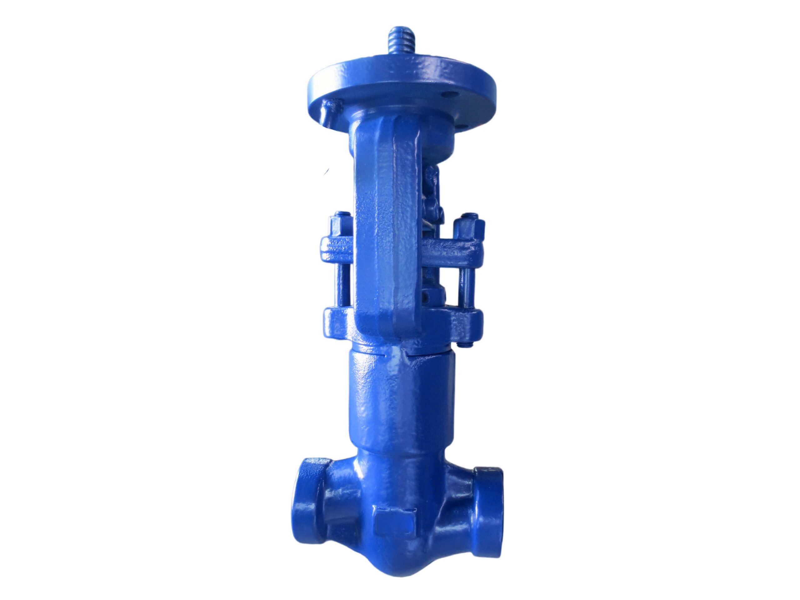
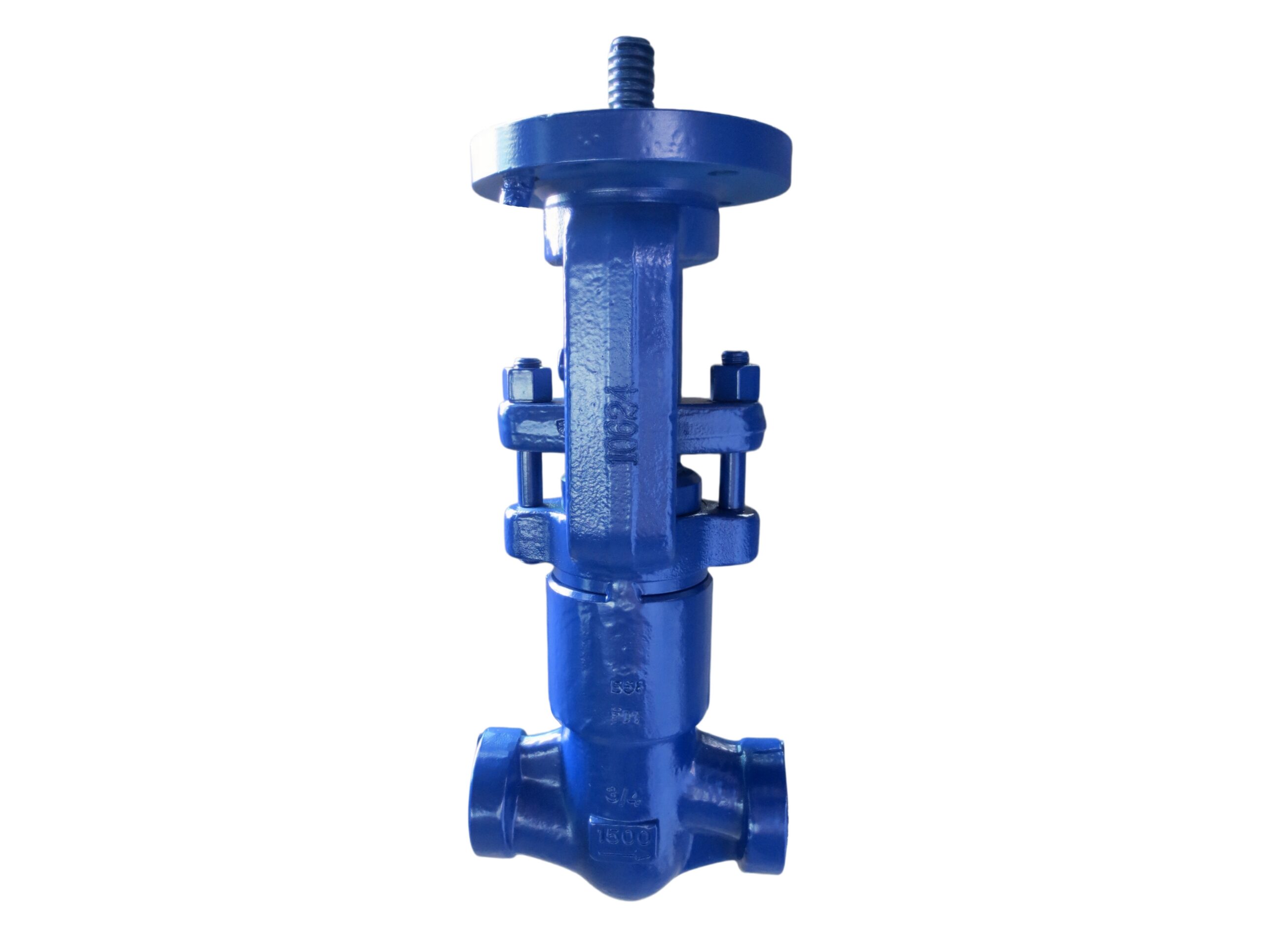
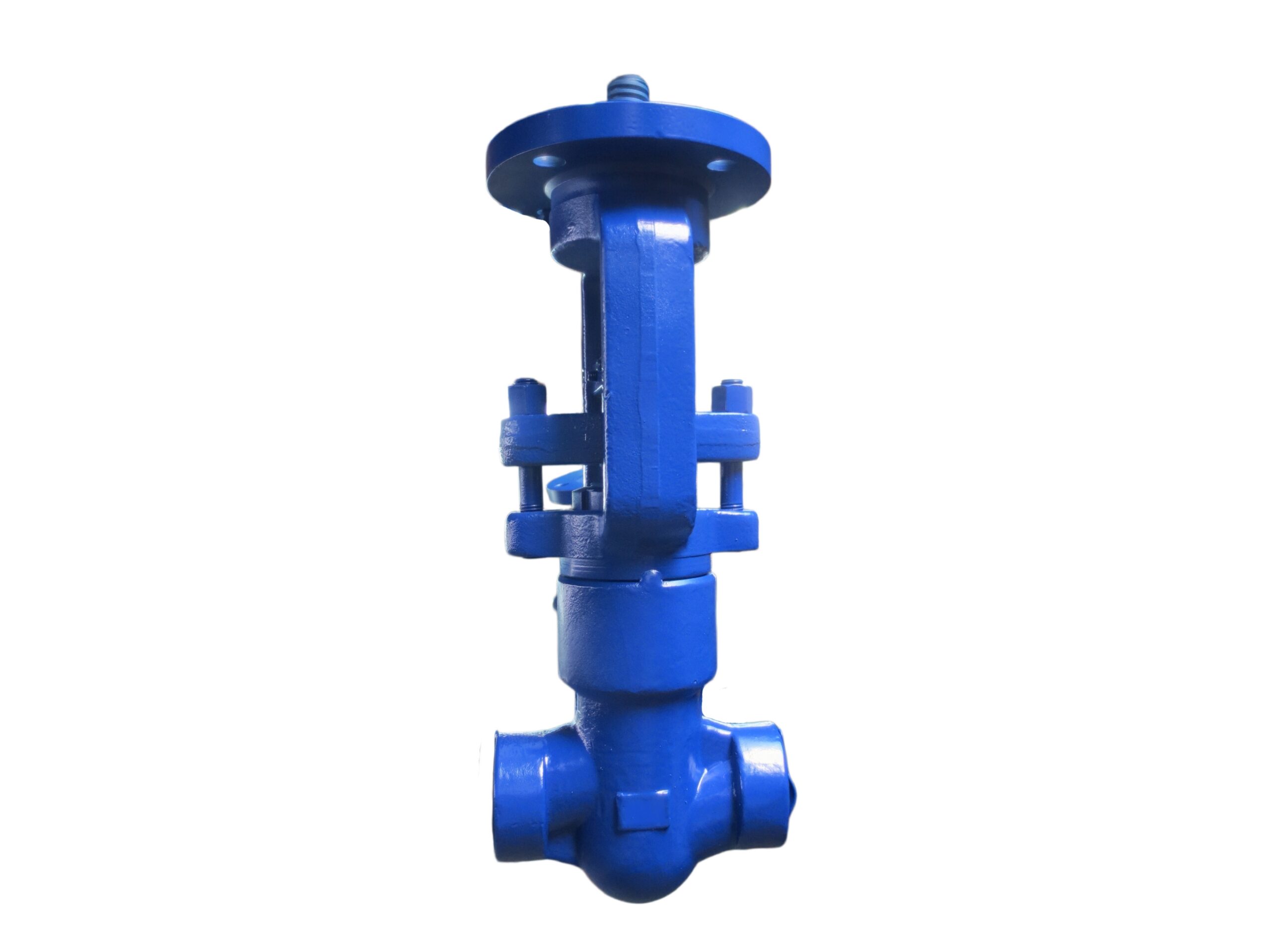
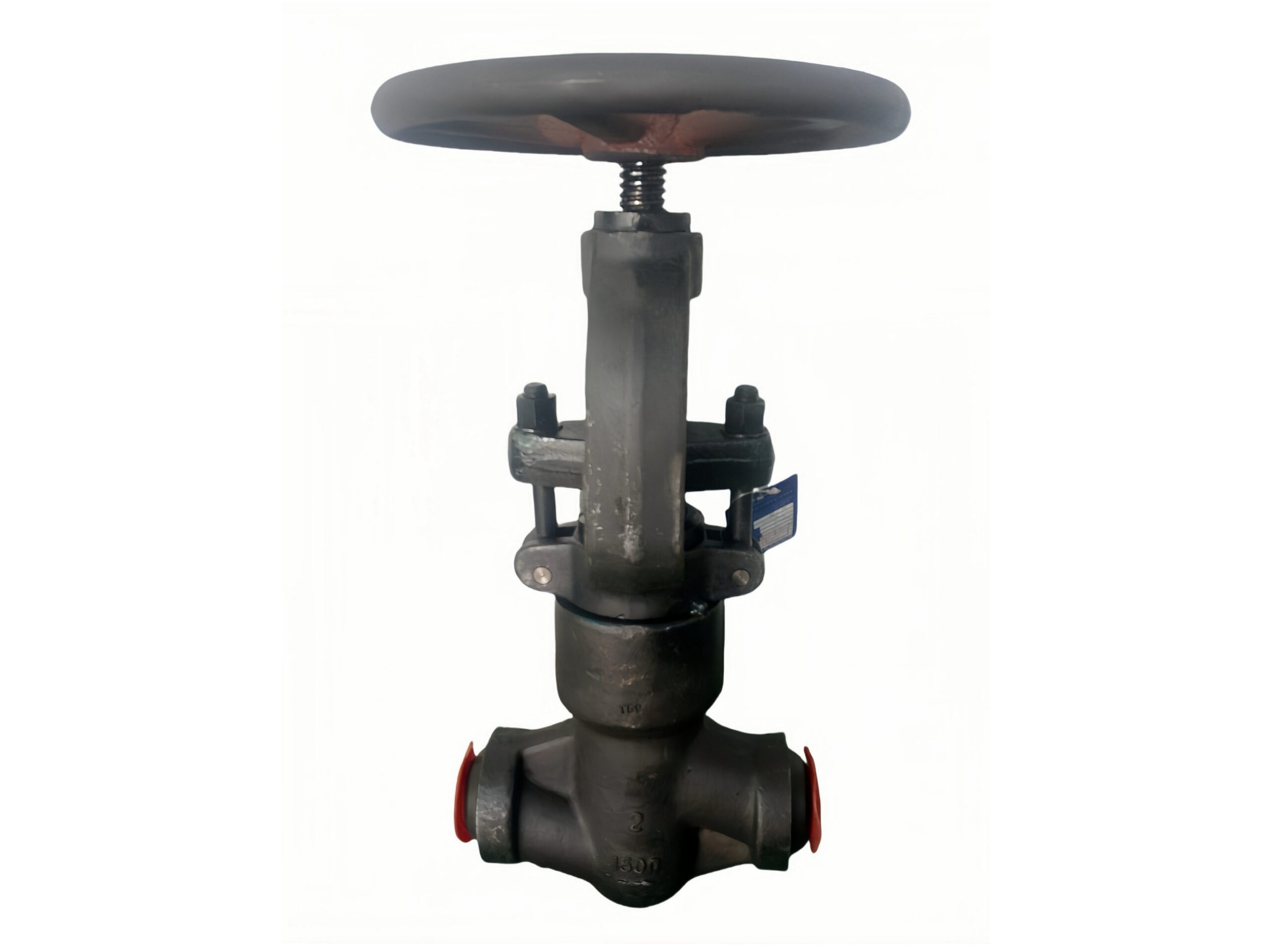
Pressure Seal Bonnet (PSB) Close Die Forged F11 Globe Valve
Description
TECHNICAL DATA SHEET
Pressure Seal Bonnet (PSB) Close Die Forged Globe Valve
Class 1500, Butt-Weld Ends, A182 F11 Body, Stellite Seated
1. GENERAL DESCRIPTION
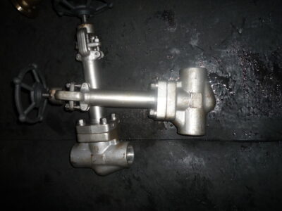
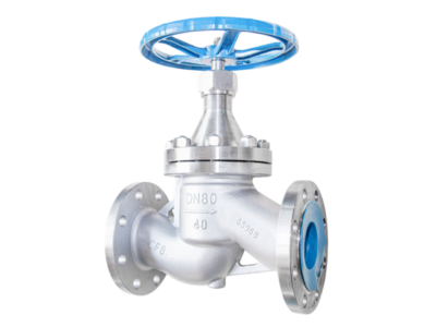
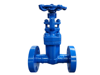
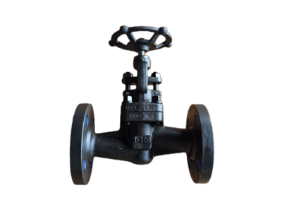
This is a heavy-duty, high-pressure globe valve featuring a Pressure Seal Bonnet (PSB) and fully close-die forged body and bonnet from ASTM A182 F11 alloy steel. The pressure seal design uses system pressure to energize the bonnet seal, creating a tight, self-reinforcing joint that becomes more effective as pressure rises. The outside screw and yoke (OS&Y) rising stem gives clear position indication, and all internal seating surfaces are hardfaced with Stellite to provide exceptional resistance to wear, erosion, and high-temperature degradation. This valve is designed for high-pressure steam, boiler feedwater, and high-temperature oil/gas applications, where strength, reliability, and safety are paramount.
2. DESIGN FEATURES
-
Pressure Seal Bonnet: The bonnet is sealed by a graphite/stainless steel gasket compressed by a segmented retaining ring and preload spacer. Pressure inside the valve further compresses the seal, ensuring a leak-tight joint at all pressures up to the valve rating.
-
Close Die Forged Construction: Body and bonnet are solid forged components with no welds or cast defects. Forging refines grain structure for superior strength and toughness compared to castings.
-
OS&Y (Rising Stem): Acme stem threads are outside the pressure boundary, protected from corrosion and easily lubricated. A backseat prevents stem blow-out and allows repacking under pressure.
-
Stellite Seating: CoCr-based hardfacing (Stellite Grade 6 or 21) deposited on seat and disc sealing faces provides outstanding hardness and galling resistance at temperatures up to 593°C.
-
Integral Body Seat: The seat is machined directly in the body and hardfaced, eliminating a separate seat ring and potential leak path.
-
Butt-Weld Ends: Ends prepared per ASME B16.25 for direct welding to matching alloy-steel pipe, providing a strong, leak-free, permanent joint.
-
Rotating Disc: The disc swivels on the stem tip to distribute wear evenly and ensure self-alignment with the seat, improving sealing over valve life.
3. APPLICABLE STANDARDS
| Category | Standard |
|---|---|
| Design & Manufacturing | API 623 (Steel Globe Valves, Pressure Seal Bonnet) |
| Pressure–Temperature Ratings | ASME B16.34 (Class 1500, Special Class per material) |
| Face-to-Face Dimensions | ASME B16.10 (Long Pattern, Class 1500) |
| End Preparation (BW) | ASME B16.25 |
| Testing & Inspection | API 598 |
| Material Specifications | ASTM A182 (Forged Alloy Steel), ASTM A276 (Stem), ASTM B16.34 |
| NACE Compliance (Option) | NACE MR0175 / ISO 15156 |
4. TECHNICAL SPECIFICATIONS
| Parameter | Value |
|---|---|
| Nominal Sizes | 1/2″ – 2″ (DN15 – DN50) standard; up to 4″ (DN100) upon request |
| Pressure Class | ASME Class 1500 |
| Maximum Working Pressure | Per ASME B16.34 for F11 at temperature (see Section 7) |
| Shell Test Pressure (Hydro) | 2.0 x CWP at 38°C = 75.8 bar (for Class 1500) per API 598 |
| Seat Leakage Test | 1.1 x CWP (water/air); metal-seated allowance per API 598 |
| Standard Temperature Range | -29 °C to +593 °C (-20 °F to +1100 °F) |
| Flow Direction | Inlet under disc (flow arrow cast/forged on body) |
| Operation | Handwheel (standard); Gearbox over 2″ or as specified |
| NDE (Optional) | Radiography (RT), Ultrasonic (UT), Dye Penetrant (PT), PMI |
5. BILL OF MATERIALS (BOM) – Standard Trim for High-Temperature Service
| No. | Component | Material | ASTM / UNS |
|---|---|---|---|
| 1 | Body | A182 F11 (1.25Cr-0.5Mo) | ASTM A182 Gr. F11 Class 2 |
| 2 | Bonnet | A182 F11 | ASTM A182 Gr. F11 Class 2 |
| 3 | Disc | A182 F11 / A105 Stellite Overlay | Stellite Gr. 6 on seating face |
| 4 | Seat (Integral) | A182 F11 + Stellite Hardface | Stellite Gr. 6 welded overlay |
| 5 | Stem | ASTM A276 Type 410 / 420 | A276 13% Cr, heat treated |
| 6 | Stem Nut (Yoke Bushing) | Bronze | C95400 (Alum. Bronze) |
| 7 | Pressure Seal Gasket | Graphite + Stainless Steel Ribbon | 304SS reinforced grafoil |
| 8 | Bonnet Retaining Ring / Segments | Alloy Steel | ASTM A434 Gr. 4140 / A182 F22 |
| 9 | Bonnet Preload Spacer | Carbon Steel | ASTM A516 Gr. 70 |
| 10 | Packing | Die-formed flexible graphite with braided ends | — |
| 11 | Gland / Gland Flange | Carbon Steel, Zinc Plated | ASTM A108 / A36 |
| 12 | Backseat Bushing | 13% Cr Stainless Steel | ASTM A276 Type 420 |
| 13 | Bonnet Studs & Nuts | ASTM A193 Gr. B16 / A194 Gr. 4 | Alloy Steel |
| 14 | Handwheel | Ductile Iron / Malleable Iron | ASTM A536 or A47 |
| 15 | Identification Plate | SS 304 | — |
Note: For sour service (NACE MR0175), stem and internal bolting are upgraded to compliant materials, typically A276 Type 410 or 316L with hardness limitation. Consult factory.
6. DIMENSIONS (Class 1500, Butt-Weld Ends, Long Pattern per ASME B16.10)
| Size (in / DN) | Face-to-Face L (mm) | Open Height H ≈ (mm) | Handwheel Dia. (mm) | Approx. Weight (kg) |
|---|---|---|---|---|
| 1/2″ (DN15) | 216 | 318 | 125 | 7.5 |
| 3/4″ (DN20) | 229 | 325 | 125 | 8.5 |
| 1″ (DN25) | 254 | 390 | 160 | 12.5 |
| 1-1/4″ (DN32) | 279 | 415 | 180 | 18 |
| 1-1/2″ (DN40) | 305 | 480 | 200 | 23 |
| 2″ (DN50) | 368 | 540 | 250 | 36 |
H is approximate open height from pipe centerline to top of handwheel. Weights are approximate. Larger sizes and gear-operated dimensions on request. Weld end details: Ends are bored to match schedule 160 pipe (standard wall) and beveled per ASME B16.25. Confirm pipe schedule when ordering.
7. PRESSURE–TEMPERATURE RATING (per ASME B16.34, A182 F11, Special Class)
| Temperature (°C) | Max. Working Pressure (bar) |
|---|---|
| -29 to 38 | 259.2 |
| 100 | 239.4 |
| 200 | 217.1 |
| 300 | 202.3 |
| 400 | 190.5 |
| 450 | 183.9 |
| 500 | 177.3 |
| 538 | 119.7 |
| 566 | 85.8 |
| 593 | 55.9 |
Ratings are for Special Class, which applies to butt-weld end valves of this material. For lower temperatures, non-shock pressure is 259.2 bar. Flanged valves or standard class ratings may be lower; check ASME B16.34 for details.
8. TESTING & INSPECTION (per API 598)
Every valve undergoes rigorous testing:
-
Shell Hydrostatic Test: 75.8 bar minimum (2.0 x MWP at 38°C for Class 1500) for 60 seconds, zero leakage.
-
Seat Leakage Test: High pressure water/air test at 1.1 x MWP (41.7 bar for Class 1500). Leakage rate per API 598 for metal-seated valves is allowed; Stellite seats are hand-lapped to achieve tight shutoff meeting or exceeding these limits.
-
Backseat Test: Shell test pressure with packing loose; no leakage from gland.
-
Optional: Pneumatic shell & seat test (6 bar air), helium leak test, NDT (RT on welds, PT/MT on forgings), positive material identification (PMI) on all alloy parts.
9. COATING & PROTECTION
-
Standard Exterior: High-temperature aluminum-based silver paint (silicone aluminum) suitable for continuous service at 400°C. Below that, standard anti-corrosion epoxy paint in black (RAL 9005) is available.
-
Stem Protection: Exposed stem threads are supplied with a protective grease and can be fitted with a stem bellows/protection tube upon request.
10. ACCESSORIES & OPTIONS
-
Gear Operator: Recommended for 2″ and larger to reduce handwheel torque; bevel gear with handwheel.
-
Chain Wheel: For overhead operation with chain guide.
-
Locking Device: Open and closed position padlock.
-
Limit Switches / Position Transmitter: For remote status monitoring.
-
Electric or Pneumatic Actuator: with ISO 5211 mounting bracket; ensure adequate torque margin.
-
NACE MR0175 Compliance: Full compliance package for sour gas/oil.
-
Bypass / Drain: Tapped and plugged drain in body available for certain sizes.
-
Extended Bonnet or Stem: For cryogenic or high-temperature insulation applications.
11. NOTES
-
The valve is metal seated (Stellite). For bubble-tight shutoff, a soft-seated valve would be required, but this is not typical for Class 1500 and high-temperature service.
-
Verify pipe schedule to ensure matching bore and weld preps. Standard ends are prepared for Schedule 160 pipe or per customer specification.
-
For applications above 538°C, consult manufacturer for possible material derating or alternative materials such as A182 F22 or F91.
-
Always install the valve with flow entering under the disc (direction arrow on body) to ensure stable throttling and prevent damage to internals.
-
Pressure seal bonnet valves must be opened prior to welding on the pipeline to prevent thermal damage to the seal gasket. After welding, the bonnet retainer bolts may need re-torquing as per manufacturer’s instructions.
All specifications are subject to change. Certified drawings, full EN 10204 3.1 material certificates, and NDT reports are available upon request. For critical applications, please specify all operating conditions for a complete engineering review.