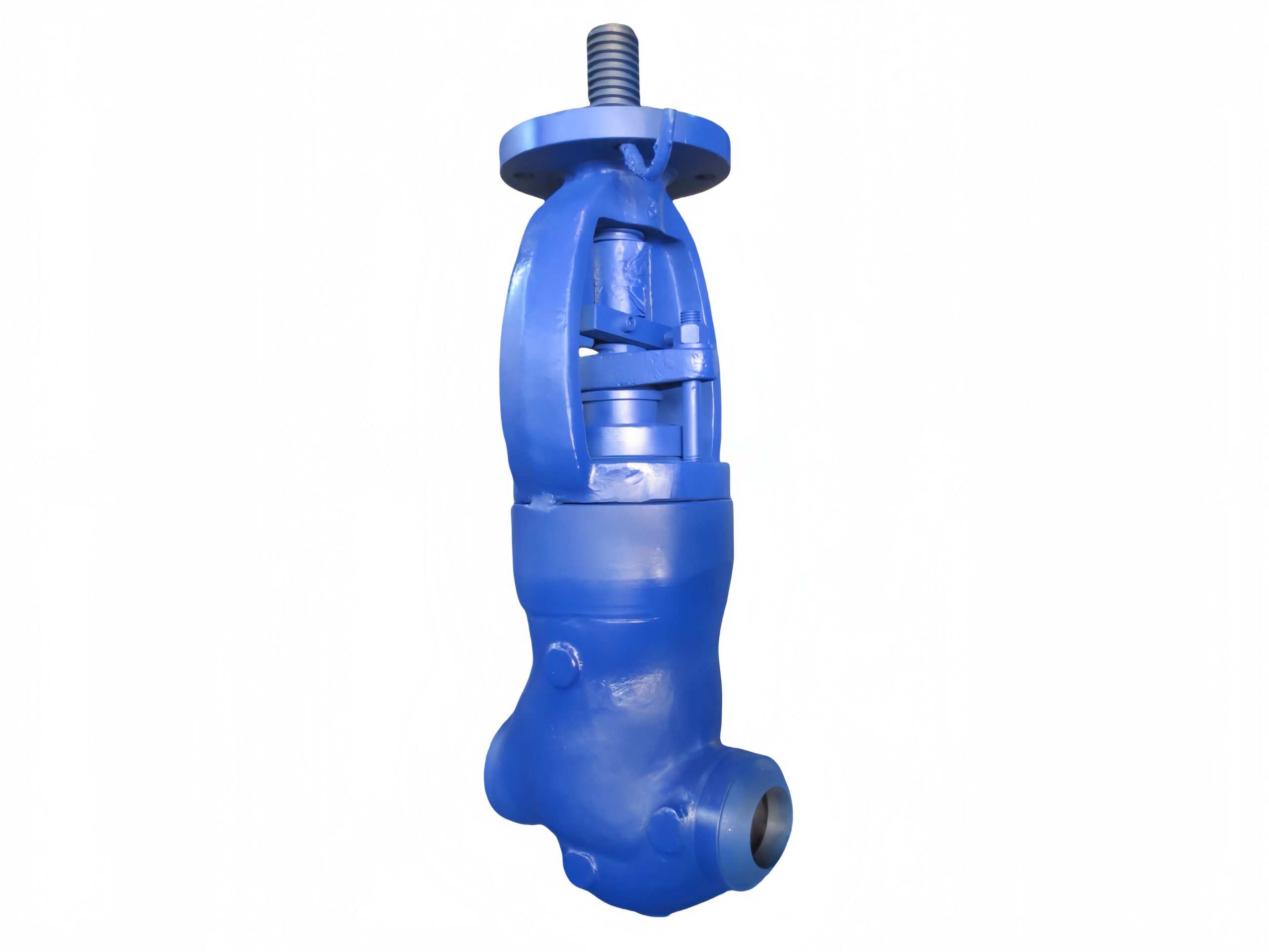
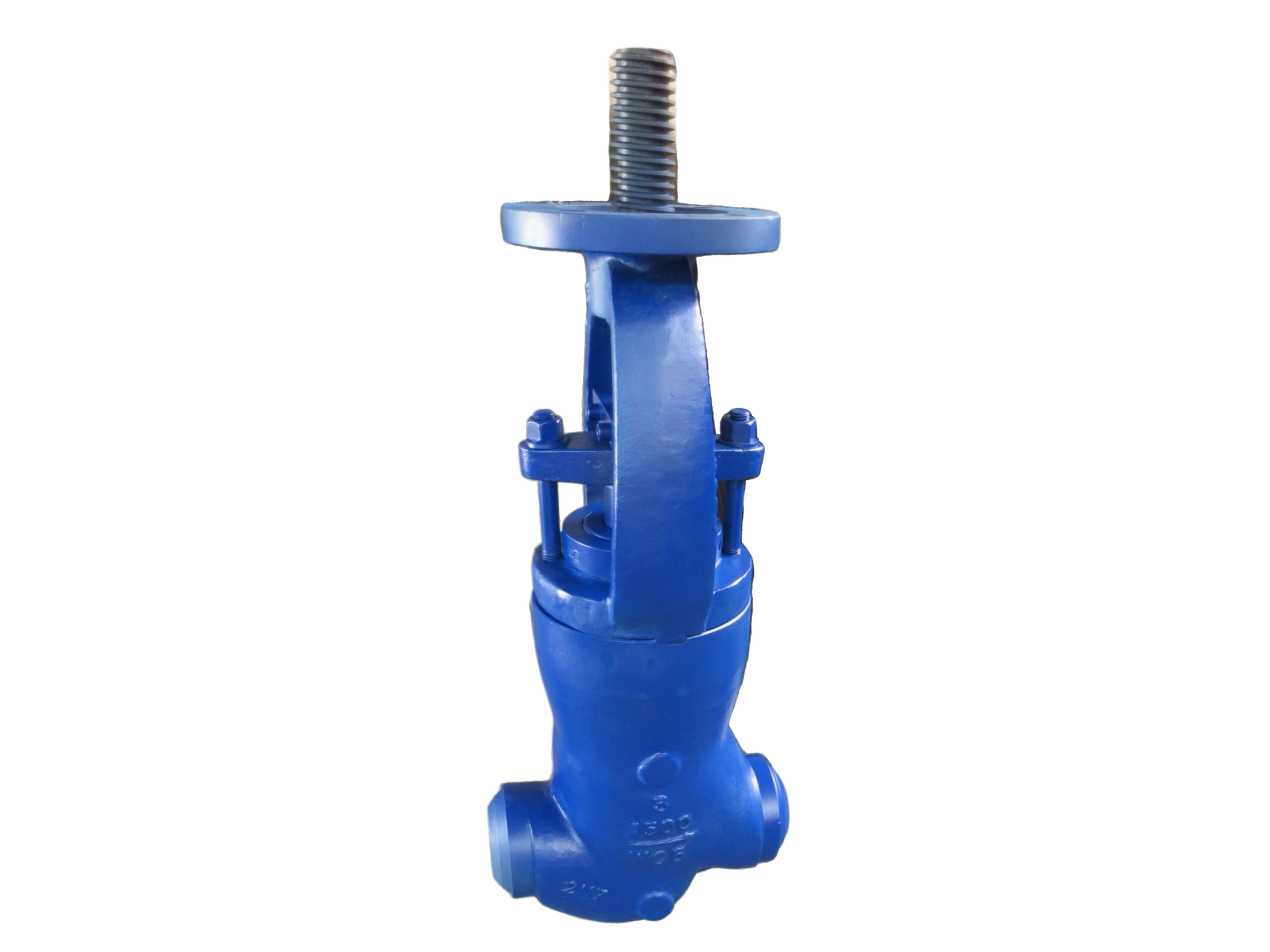
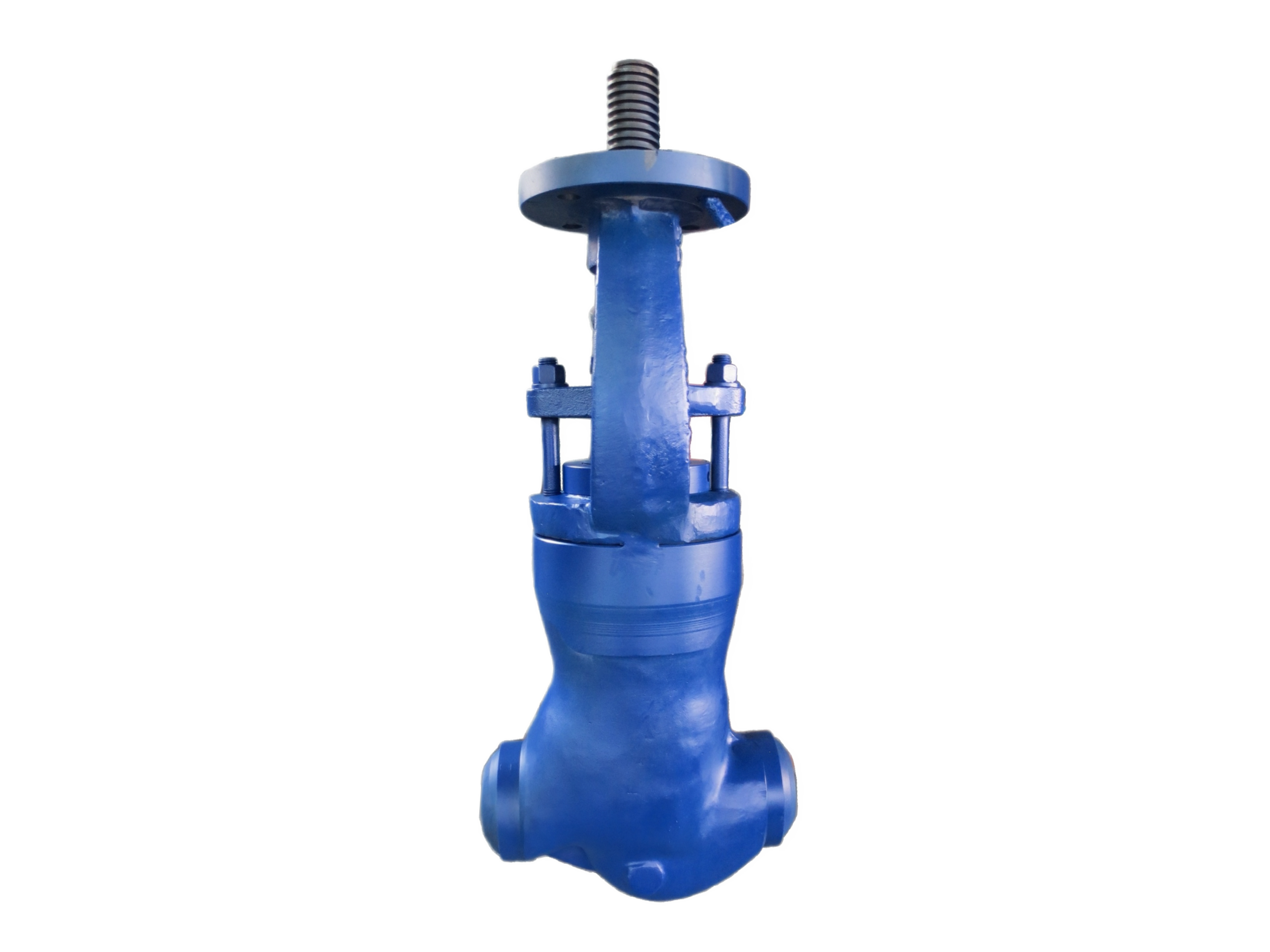
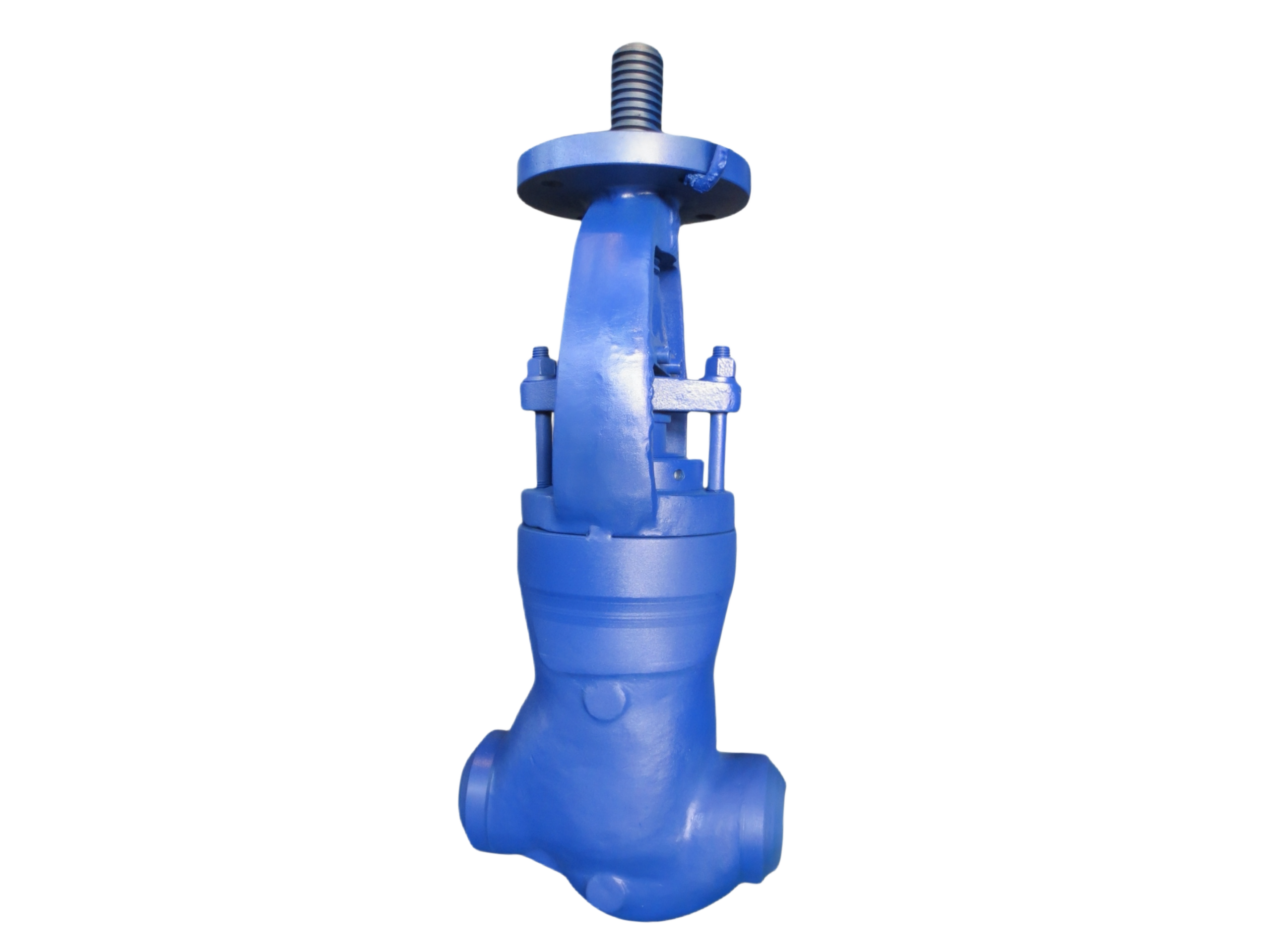
PSB Globe Valve—3″ 1500LB BW WC6
Description
Technical Data Sheet
Pressure Seal Bonnet (PSB) Globe Valve
Size & Class: 3″ 1500LB
End Connection: Butt-Weld (BW)
Body Material: ASTM A217 WC6
1. General Description
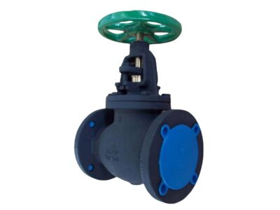
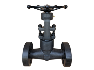
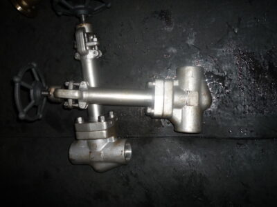
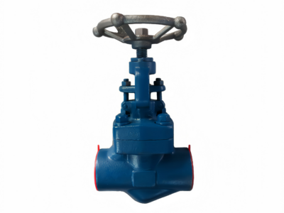
This is a cast steel globe valve with a pressure seal bonnet (PSB) . The body and bonnet are cast from ASTM A217 WC6 chromium-molybdenum alloy steel, providing excellent high-temperature strength and creep resistance. The disc and seat sealing faces are overlayed with Stellite 6 hardfacing. The stem is precision machined and surface hardened. The valve features an outside screw and yoke (OS&Y) design, handwheel operation (actuator-mountable as an option), and butt-weld ends prepared to ASME B16.25. It is designed for high-temperature, high-pressure services such as thermal power plants, petrochemical processes, and steam systems, with a maximum service temperature of +540 °C (+1000 °F) .
2. Design Codes & Standards
Item Applicable Standard
Design & Manufacture ASME B16.34, BS 1873, API 623
Pressure-Temperature Rating ASME B16.34 (WC6 material group)
Butt-Weld Ends ASME B16.25
Face-to-Face Dimensions ASME B16.10 (Long Pattern)
Inspection & Testing API 598
Casting Standard ASTM A217 (WC6)
Pressure Seal Bonnet Manufacturer’s standard in accordance with ASME B16.34 requirements
3. Main Technical Specifications
Nominal Size: 3″ (DN80)
Pressure Class: Class 1500 (1500LB)
End Connection: Butt-Weld (BW)
Body Material: ASTM A217 WC6
Bonnet Material: ASTM A217 WC6 (Pressure Seal Type)
Disc Type: Conical or parabolic plug disc
Disc / Seat Sealing Face: Stellite 6 Overlay
Stem Material: ASTM A182 F6a (13Cr) or 17-4PH
Packing: Flexible Graphite (with braided graphite end rings)
Pressure Seal Gasket: Pure Graphite with SS316 retaining ring
Operation: Handwheel (electric/pneumatic actuators optional)
Service Media: Steam, high-temperature water, oil, gas, and other non-corrosive or mildly corrosive fluids
Temperature Range: -29 °C to +540 °C (-20 °F to +1000 °F)
4. Materials of Major Parts
No. Part Name Material Standard
1 Body A217 WC6 ASTM A217
2 Bonnet A217 WC6 ASTM A217
3 Disc A182 F11 / WC6 + STL.6 Overlay ASTM A182 / A217
4 Seat Integral STL.6 Overlay —
5 Stem A182 F6a (13Cr) ASTM A182
6 Packing Flexible Graphite —
7 PS Gasket Graphite + SS316 Retaining Ring —
8 Segmental Ring / Retainer AISI 4140 / Alloy Steel —
9 Stem Nut Aluminum Bronze / Alloy Steel —
10 Handwheel Carbon Steel (Zinc Plated) —
11 Yoke A216 WCB / WC6 ASTM A216 / A217
12 Gland & Bolts A276 410 / Alloy Steel —
5. Principal Dimensions (3″ 1500LB BW)
Symbol Description Value (mm) Value (inch)
L Face-to-Face / End-to-End 368 14.50″
d BW End OD (for SCH 160) 88.9 3.50″
d1 BW End ID (approx.) 66.6 2.62″
H (approx.) Centerline to Top of Handwheel ~520 ~20.5″
HW Dia. Handwheel Diameter ~350 ~13.8″
Weight Approx. Weight ~95 kg —
Weld Bevel Per ASME B16.25 Compound Bevel —
*Note: Face-to-face dimensions conform to ASME B16.10 Long Pattern. Height and weight are approximate; final values are confirmed on the approved drawing. BW end wall thickness matches mating pipe, typically SCH 160 or as designed.*
6. Performance Tests & Inspection
Shell Strength Test: 1.5 × Class 1500 rated pressure (approx. 264 bar / 3830 psi), hold time ≥1 minute, no leakage or permanent deformation.
High-Pressure Seat Test: 1.1 × rated pressure (approx. 194 bar / 2810 psi), water, zero leakage.
Low-Pressure Seat Test: 0.6 bar pneumatic, zero leakage.
Stem Operation: Handwheel operates smoothly without sticking; disc and seat alignment is confirmed.
Casting Inspection: 100% visual and dimensional check. Dye penetrant (PT) on critical areas; ultrasonic (UT) or radiographic (RT) testing available per customer request.
Material Certification: EN 10204 Type 3.1 material certificates provided; PMI spectral analysis optional.
7. Installation & Maintenance Tips
Welding Installation: The BW ends should match the pipe material or be welded using an approved procedure. The valve must be in the fully closed position during welding to protect the seating surfaces from weld spatter. For WC6 material, preheat to above 200 °C before welding, allow slow cooling after welding, and perform any required post-weld heat treatment (PWHT).
Flow Direction: Install per the arrow on the body, typically “flow under the disc” (medium enters below the disc). This ensures tight shutoff and operational safety.
Insulation: Do not cover the handwheel and yoke area with insulation during high-temperature service to allow heat dissipation and stem lubrication maintenance.
Pressure Seal Bonnet: Before disassembling the bonnet, ensure all cavity pressure is completely released. The PS bonnet achieves a tight seal by utilizing system pressure. Replace the pressure seal gasket every time the bonnet is opened and evenly tighten the gland/retaining bolts according to the manufacturer’s instructions.
Packing: For high-temperature service, re-tighten the packing gland evenly after the initial heat-up cycle to prevent leakage. Periodically inspect and replace packing under live-load conditions if permitted.
This technical data sheet is for selection reference only. The manufacturer reserves the right to change the design without prior notice. All final dimensions, materials, and technical requirements are subject to the approved order-specific drawing and technical agreement.