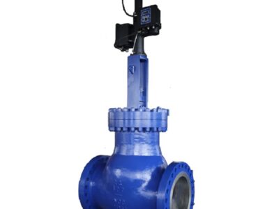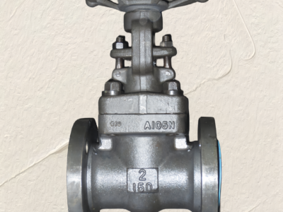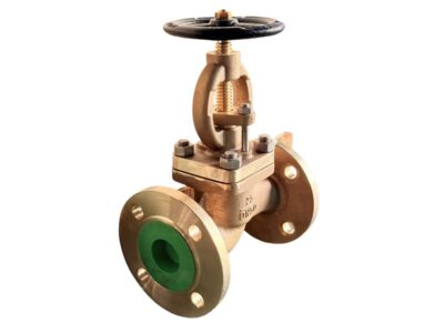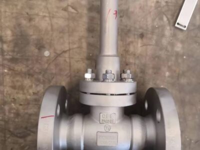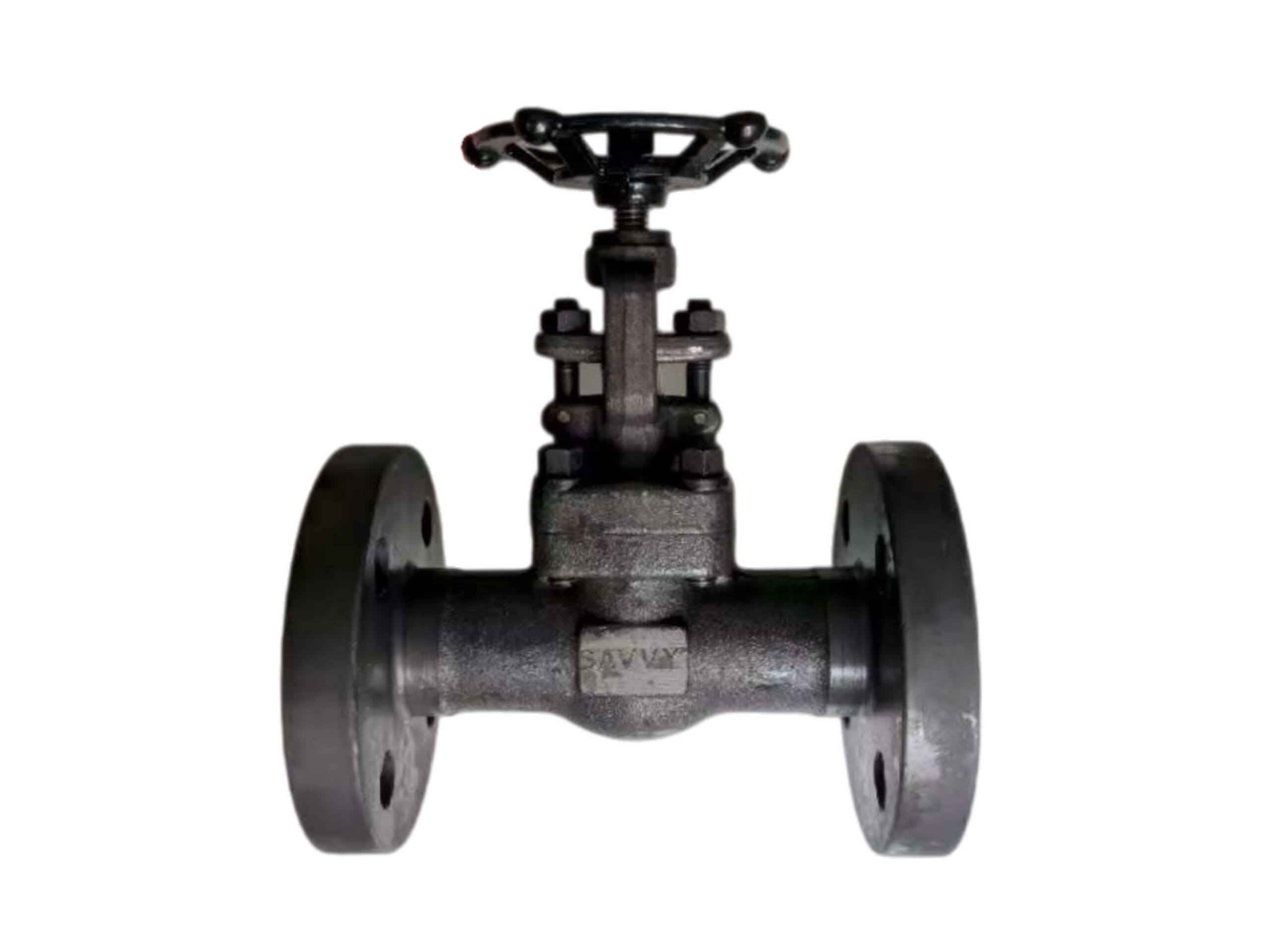
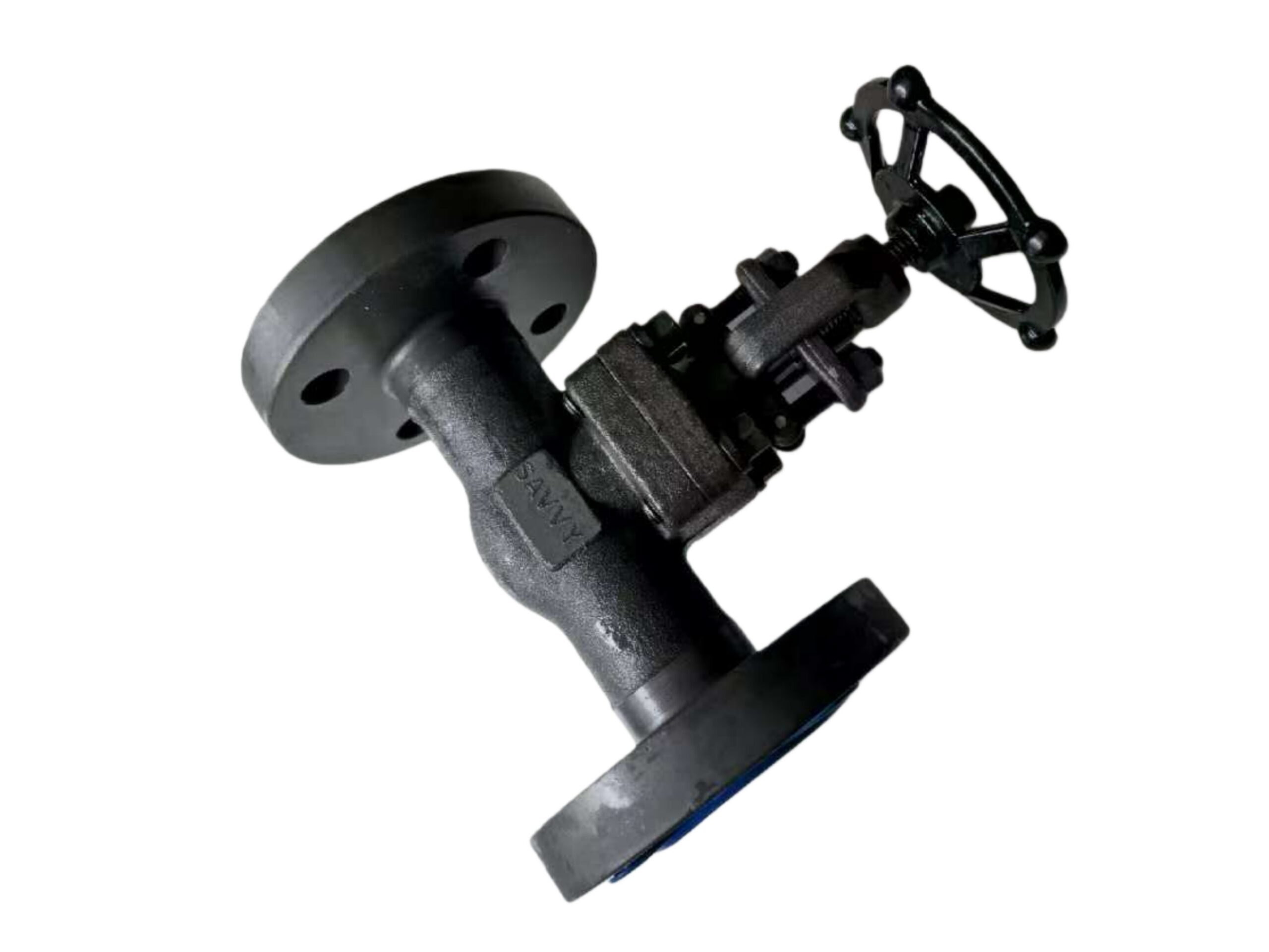
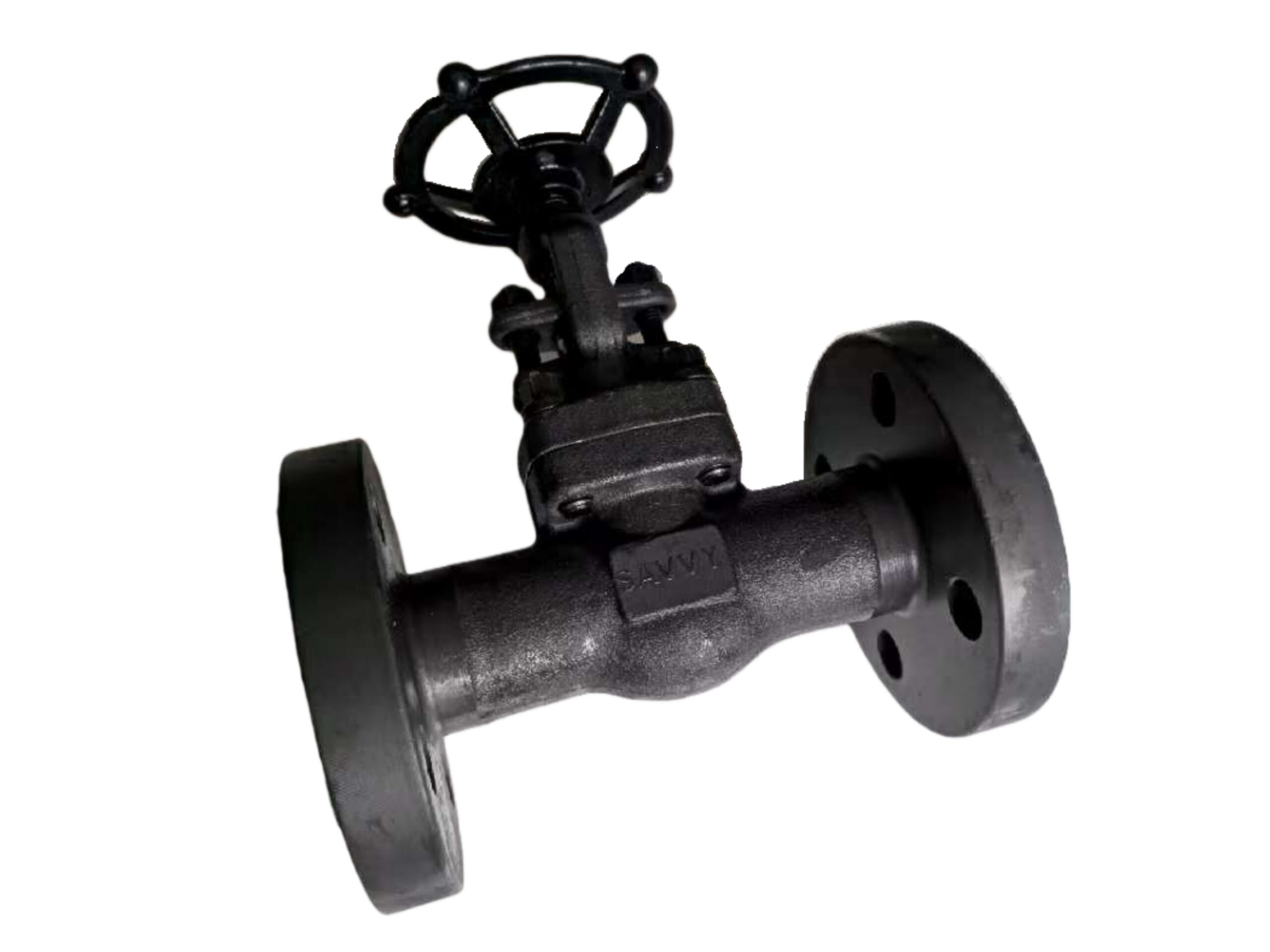
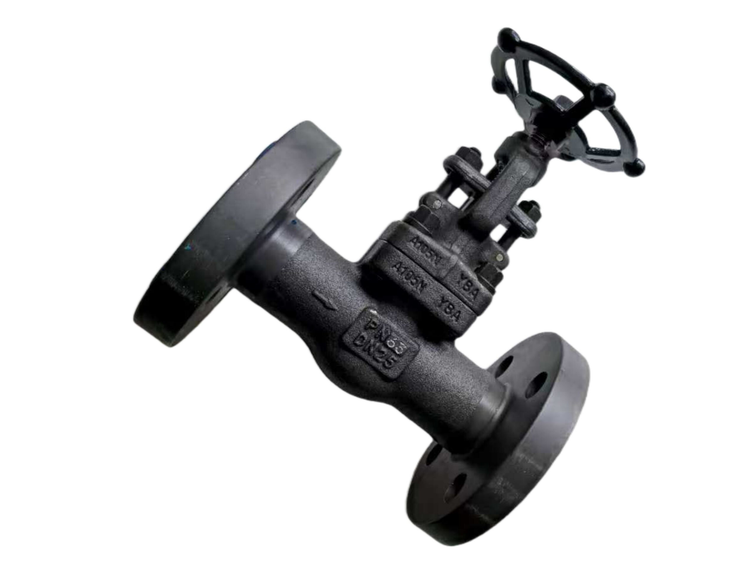
Close Die Forged A105N Globe Valve DN25-PN63-RF
Description
TECHNICAL DATA SHEET
Close Die Forged Globe Valve
DN25, PN63, A105N Body, Stellite Seated, Bolted Bonnet, OS&Y
1. GENERAL DESCRIPTION
This DN25 (1″) PN63 globe valve features a fully close-die forged body and bolted bonnet in ASTM A105N carbon steel. The valve is designed for high-pressure, non-corrosive services such as steam, feedwater, gas, and oil. The outside screw and yoke (OS&Y) configuration provides visual position indication and keeps the stem threads outside the fluid stream. All seating surfaces are hardfaced with Stellite Grade 6 for excellent resistance to wear, galling, and high-temperature erosion. The valve offers reliable metal-to-metal shutoff and is suitable for throttling, isolation, and frequent operation.
2. DESIGN FEATURES
-
Close Die Forging: Body and bonnet are forged for superior structural integrity, eliminating cast defects and providing uniform grain structure.
-
Bolted Bonnet: Secure body-bonnet joint with a fully confined graphite/stainless steel gasket for easy maintenance.
-
OS&Y Rising Stem: External Acme threads, handwheel indication, and backseat for repacking under pressure.
-
Metal Seated (Stellite Hardfaced): Integral body seat and disc face overlay of Stellite Gr.6 ensuring durability at high temperatures and pressures.
-
Rotating Disc: The disc swivels on the stem tip for even wear and perfect alignment with the seat.
-
Graphite Packing: Die-formed graphite rings with braided anti-extrusion ends for leak-free stem sealing across the full temperature range.
3. APPLICABLE STANDARDS
| Category | Standard |
|---|---|
| Design & Manufacturing | API 602 / EN 13709 (Small Bore Forged Steel Globe Valves) |
| Face-to-Face Dimensions | EN 558-1 Series 1 (Long Pattern, 250 mm) |
| Flange Connection | EN 1092-1 Type B1, PN63 (Raised Face) |
| Pressure–Temperature Ratings | EN 1092-1 PN63 (Material Group 3E0) |
| Testing & Inspection | EN 12266-1 (Shell: Rate A, Seat: Rate C) |
| Material Specifications | ASTM A105N, ASTM A276, Stellite Gr.6 |
4. TECHNICAL SPECIFICATIONS
| Parameter | Value |
|---|---|
| Nominal Diameter (DN) | DN25 (1″) |
| Nominal Pressure (PN) | PN63 (63 bar) |
| Maximum Working Pressure | 63 bar (see Pressure-Temperature section) |
| Shell Test Pressure | 94.5 bar (1.5 x PN63) |
| Seat Leakage Test | 69.3 bar (1.1 x PN63) water; EN 12266-1 Rate C |
| Allowable Leakage Rate | Metal-seated allowance per EN 12266-1 Rate C |
| Temperature Range | -29 °C to +425 °C (-20 °F to +800 °F) |
| Flow Direction | Unidirectional (arrow on body) – Inlet under the disc |
| Operation | Manual Handwheel |
| Coating | Anti-corrosion black epoxy paint (RAL 9005) |
5. BILL OF MATERIALS (BOM)
| No. | Component | Material | ASTM / EN Grade |
|---|---|---|---|
| 1 | Body | Carbon Steel Forging (Normalized) | ASTM A105N |
| 2 | Bonnet | Carbon Steel Forging (Normalized) | ASTM A105N |
| 3 | Disc | ASTM A105N + Stellite Gr.6 facing | Hardness ≥ 38 HRC on seat face |
| 4 | Seat (Integral) | ASTM A105N + Stellite Gr.6 overlay | Stellite Gr.6 |
| 5 | Stem | Stainless Steel 13% Cr | ASTM A276 Type 420 (heat treated) |
| 6 | Stem Nut / Yoke Bushing | Aluminum Bronze / Brass | ASTM B148 C95400 |
| 7 | Bonnet Gasket | Graphite + SS 316L reinforced | — |
| 8 | Packing Set | Flexible graphite rings with braided ends | — |
| 9 | Gland / Gland Flange | Carbon Steel | ASTM A105N / A36 |
| 10 | Backseat Bushing | Stainless Steel 13% Cr | ASTM A276 Type 420 |
| 11 | Bonnet Bolts & Nuts | Alloy Steel / Carbon Steel Zn Plated | A193 Gr.B7 / A194 Gr.2H |
| 12 | Handwheel | Malleable Iron / Cast Iron | — |
| 13 | Identification Plate | SS 304 | — |
Note: Optional NACE MR0175 compliance for sour service requires hardness restrictions on stems and internal bolting. Consult factory.
6. DIMENSIONS (DN25, PN63, Flanged Ends)
| Symbol | Description | Dimension |
|---|---|---|
| L | Face-to-Face (EN 558-1 Series 1) | 250 mm |
| D_flange | Flange Outer Diameter | 140 mm |
| D_bolt circle | Flange Bolt Circle | 100 mm |
| Bolt Holes | 4 x M16 / 18 mm | |
| H_open | Center of pipe to top of handwheel (approx.) | 305 mm |
| W | Handwheel Diameter | 160 mm |
| Weight | Approx. | 12 kg |
For butt-weld end connection, the face-to-face length is typically 254 mm and ends prepared per ASME B16.25 or EN 12627. Confirm when ordering.
7. PRESSURE–TEMPERATURE RATING (EN 1092-1, PN63, A105N / Group 3E0)
| Temperature (°C) | Max. Working Pressure (bar) |
|---|---|
| -29 to +50 | 63.0 |
| 100 | 62.1 |
| 200 | 56.8 |
| 250 | 52.9 |
| 300 | 49.0 |
| 350 | 45.1 |
| 400 | 41.2 |
| 425 | 39.0 |
For temperatures above 425°C, alloy steel (A182 F11 / F22) is required. Not recommended for continuous operation below -29°C without impact-tested materials.
8. TESTING & INSPECTION (per EN 12266-1)
-
Shell Hydrostatic Test: 94.5 bar for minimum 60 seconds. No visible leakage allowed.
-
Seat Leakage Test: 69.3 bar water. Leakage rate shall not exceed EN 12266-1 Rate C limits for metal seated globe valves.
-
Backseat Test: Shell test pressure with packing loose, zero leakage from gland.
-
Optional: Pneumatic test (6 bar air), liquid penetrant (PT) or magnetic particle (MT) inspection on forgings, positive material identification (PMI).
9. COATING & PROTECTION
-
Exterior: High-build two-component epoxy paint, RAL 9005 (Jet Black), min. DFT 150 μm. Other colours available.
-
Stem: Polished working surface; exposed threads greased and covered with a stem protector.
-
Flanges: Raised face with protective coating and end caps during transit.
10. ACCESSORIES & OPTIONS
-
End Connection: Butt-Weld ends (BW), Socket Weld (SW), or Threaded (NPT) available on request.
-
Gearbox: Not required for DN25; available for larger sizes.
-
Locking Device: Padlockable handwheel in open or closed position.
-
Limit Switches / Positioner: Mechanical or proximity switches for remote indication.
-
Electric or Pneumatic Actuator: Mounting bracket according to ISO 5211 (flange size F05 or F07).
-
Material Upgrade: Full stainless steel body (A182 F316) for corrosive fluids.
-
Cryogenic Extension Bonnet: For low temperature services (down to -196°C).
11. NOTES
-
The valve is metal seated. A small leakage is permissible per EN 12266-1 Rate C. For zero-leakage (bubble-tight) shutoff, a soft-seated valve (e.g., PTFE or PEEK) must be specified, which will be limited to lower temperatures.
-
Install with flow direction as indicated by the arrow on the body—fluid must enter under the disc to ensure stable throttling and smooth operation.
-
For dead-end service, the maximum differential pressure must not exceed the rated seat test pressure.
-
During installation, ensure proper alignment and support to avoid induced stress on the valve body. Do not use the handwheel as a lifting point.
-
Regular inspection of packing and handwheel torque is recommended for steam and high-cycle applications.
All data is based on standard production; specifications may change without notice. Certified dimensioned drawings, EN 10204 3.1 material certificates, and test reports are available upon request.