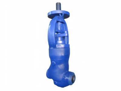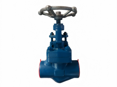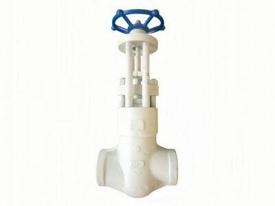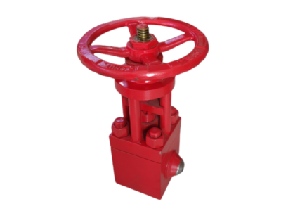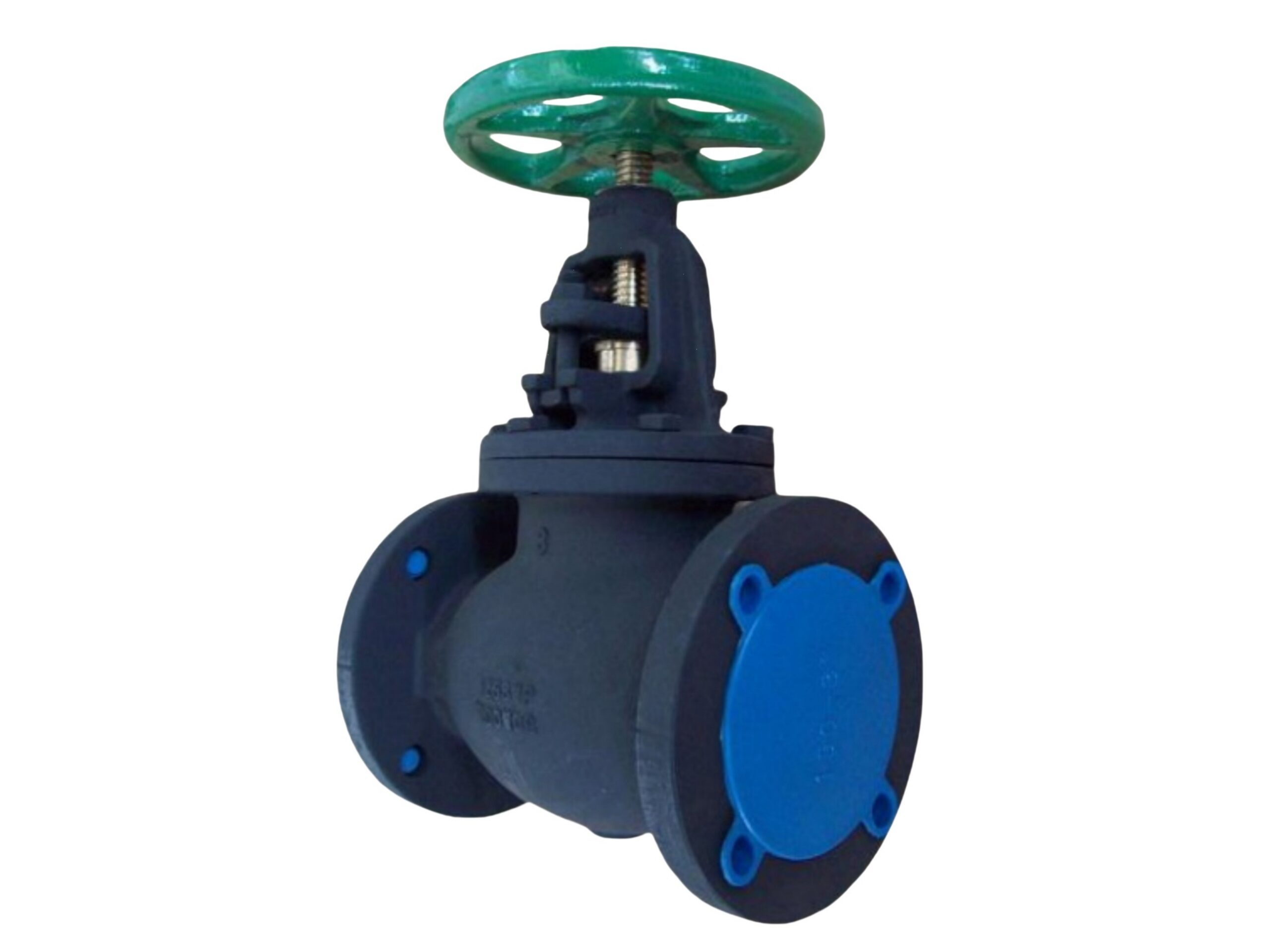
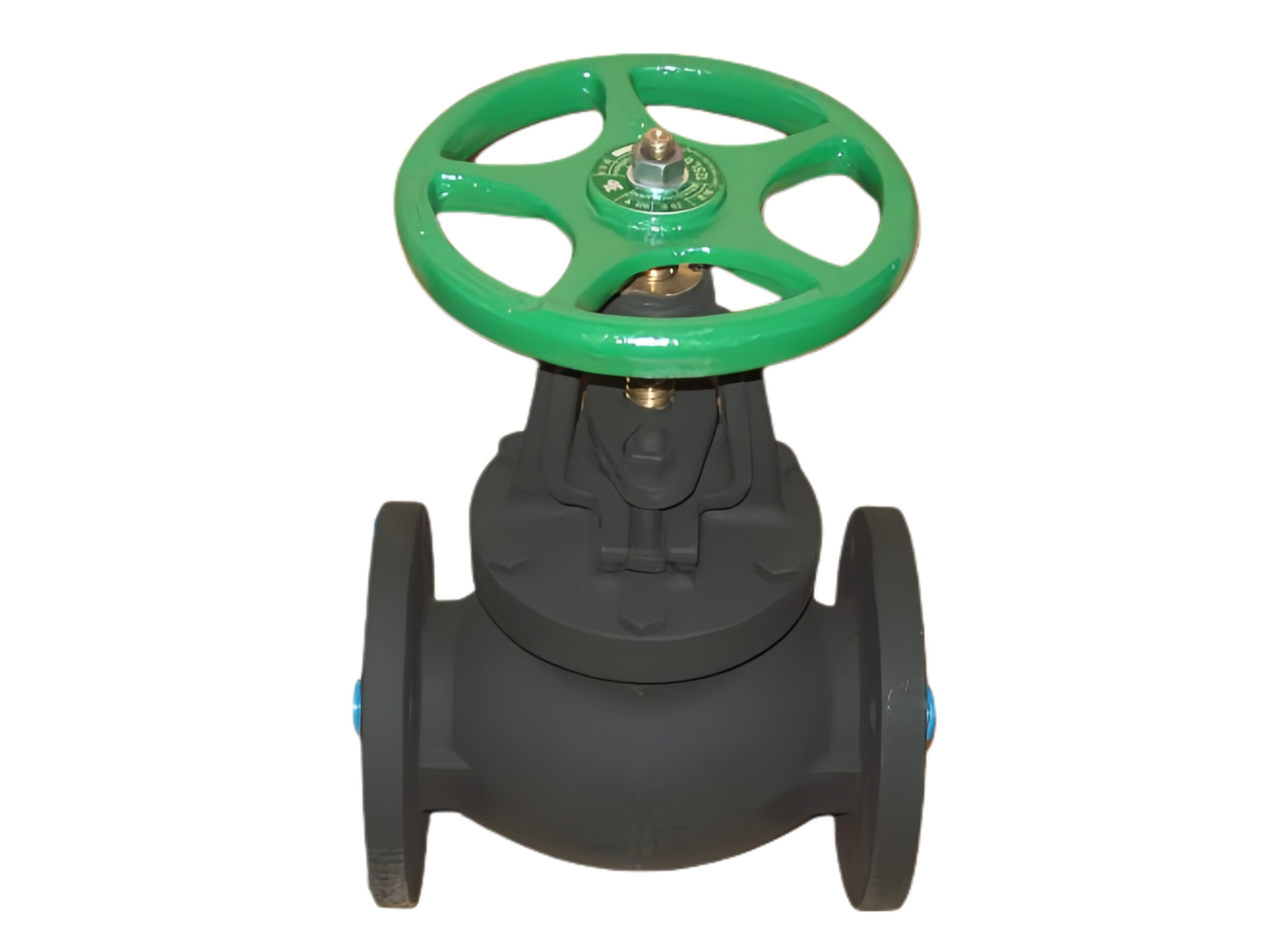
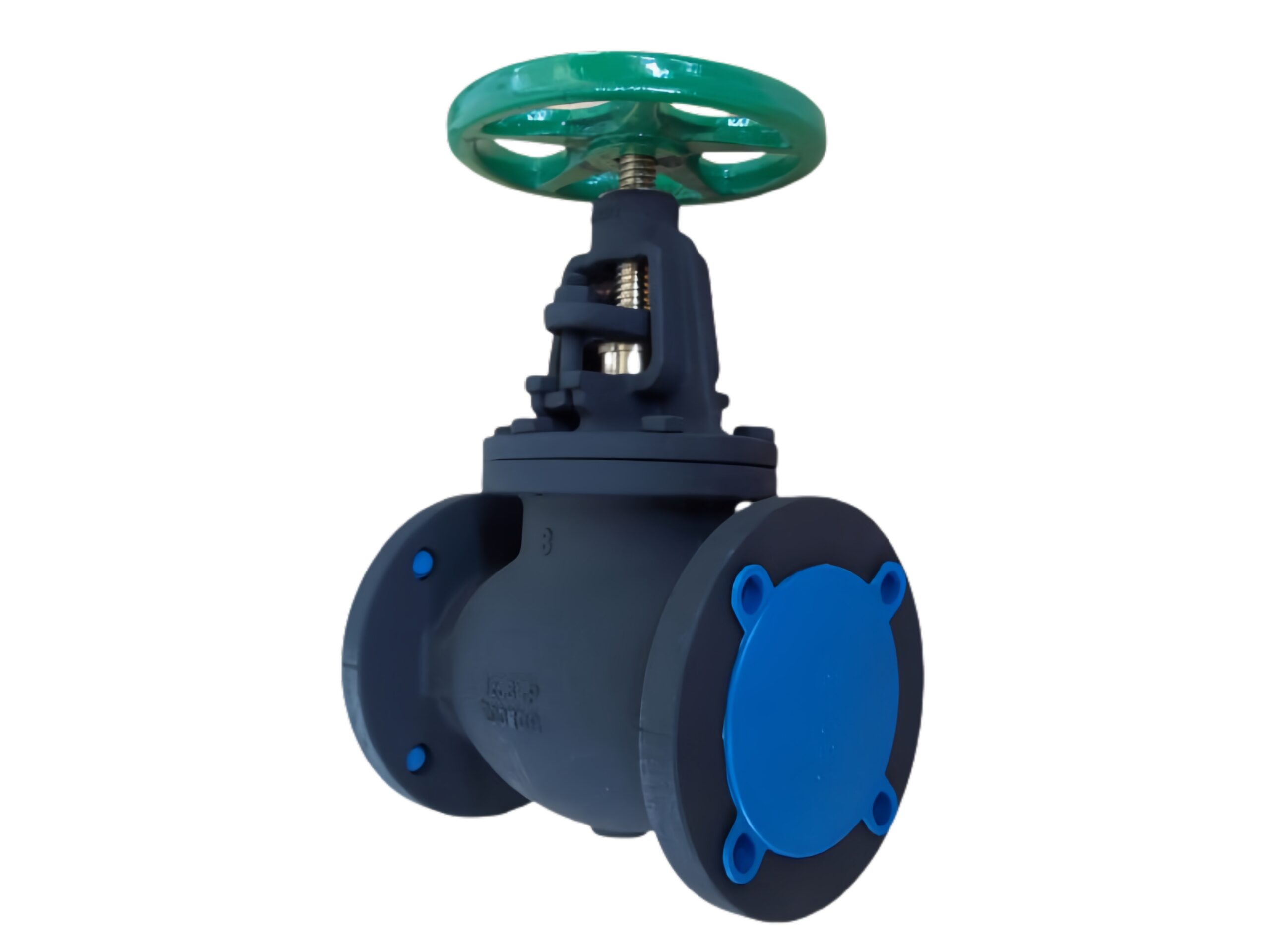
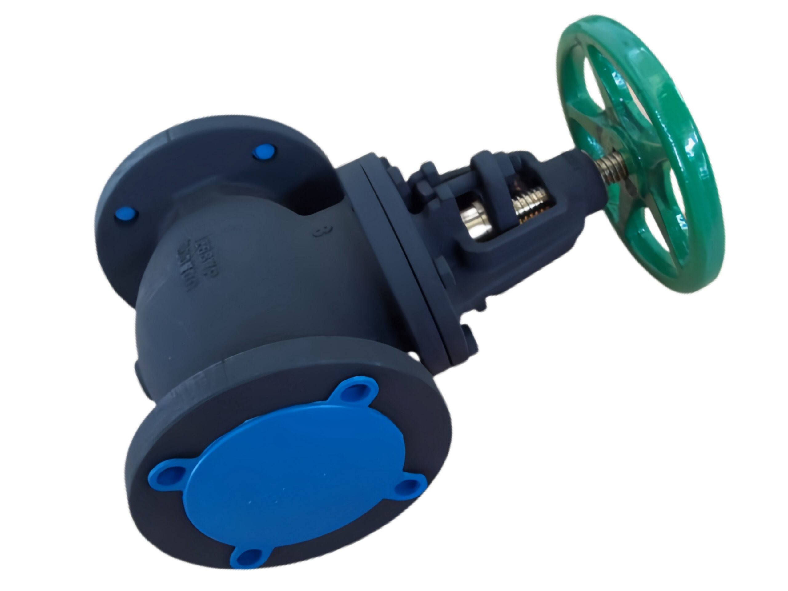
Heavy-duty Cast Iron Metal Seated Globe Valve
Description
TECHNICAL DATA SHEET
Heavy-Duty Ductile Iron Globe Valve
Metal Seated, Bronze Trim, Bolted Bonnet, OS&Y, Flanged Ends
Design Standard: MSS SP-85
1. GENERAL DESCRIPTION
This heavy-duty, bolted bonnet globe valve is designed to MSS SP-85 using a ductile iron body and bonnet for superior strength and impact resistance. The renewable bronze seat ring and bronze disc provide reliable metal-to-metal shutoff, making it ideal for steam, hot water, compressed air, and industrial fluids. The Outside Screw and Yoke (OS&Y) design rises visibly, keeping stem threads clear of the flow, and the backseat feature allows repacking under full pressure. The straight pattern flow contour provides efficient throttling and isolation.
2. DESIGN FEATURES
-
MSS SP-85 Compliance: Face-to-face, flange dimensions, pressure-temperature ratings, and testing meet this industry standard for cast iron globe valves.
-
OS&Y (Rising Stem): Acme threads outside the pressure boundary give clear visual position indication and remain lubricated and clean.
-
Metal Seated: Threaded-in renewable bronze seat ring and bronze disc deliver hard, long-wearing sealing faces suitable for steam and high temperatures.
-
Bolted Bonnet with Confined Gasket: Secure, serviceable body-bonnet connection using a reinforced graphite/stainless steel gasket.
-
Backseat: Precision machined backseat in the bonnet allows packing replacement while the valve is fully open and pressurized.
-
Graphite Packing: High-purity die-formed graphite rings with braided anti-extrusion rings for continuous leak-tight operation up to 260°C.
3. APPLICABLE STANDARDS
| Category | Standard |
|---|---|
| Design & Manufacturing | MSS SP-85 (Gray Iron Globe & Angle Valves, Flanged & Threaded) – applied to ductile iron construction |
| Face-to-Face Dimensions | MSS SP-85 / ASME B16.10 (Long Pattern, Class 150) |
| Flange Drilling & Facing | ASME B16.42 (Ductile Iron, Class 150, Raised Face) |
| Pressure–Temperature Ratings | ASME B16.42 Class 150 |
| Testing & Inspection | API 598 |
| Material Specifications | ASTM A536 (Ductile Iron), ASTM B62 (Bronze) |
4. TECHNICAL SPECIFICATIONS
| Parameter | Value |
|---|---|
| Nominal Size | 1/2″ – 8″ (DN15 – DN200) |
| Pressure Class | ASME Class 150 (PN20) |
| Maximum Working Pressure (MWP) | 19.6 bar @ 38°C (285 psi) |
| Shell Test Pressure | 30 bar (1.5 x MWP, per API 598) |
| Seat Leakage Test | 21 bar air/water; leakage per API 598 (metal-seated allowance) |
| Temperature Range | -10 °C to +260 °C with graphite packing |
| Flow Direction | Inlet under disc (flow arrow cast on body) |
| Operation | Handwheel (standard); gearbox optional for 6″ and larger |
| Coating | High-build anti-corrosive paint (RAL 9005 Black) |
5. BILL OF MATERIALS (BOM)
| No. | Component | Material | ASTM / UNS |
|---|---|---|---|
| 1 | Body | Ductile Iron | ASTM A536 Grade 65-45-12 |
| 2 | Bonnet | Ductile Iron | ASTM A536 Grade 65-45-12 |
| 3 | Disc (Solid Bronze) | Bronze | ASTM B62 C83600 |
| 4 | Seat Ring (Renewable) | Bronze | ASTM B62 C83600 |
| 5 | Stem | Stainless Steel | ASTM A276 Type 410 / 420 |
| 6 | Stem Nut / Yoke Bushing | Bronze / High-Strength Brass | C95500 / C89835 |
| 7 | Bonnet Gasket | Graphite with SS316 insert | – |
| 8 | Packing | Pure graphite rings + braided carbon ends | – |
| 9 | Gland & Gland Flange | Carbon Steel / Ductile Iron | – |
| 10 | Backseat Bushing | Stainless Steel | 13% Cr (420) |
| 11 | Bonnet Bolts & Nuts | Carbon Steel Zn-Plated / SS304 | Grade 8 / A2-70 |
| 12 | Handwheel | Cast Iron / Ductile Iron | – |
6. DIMENSIONS (Class 150, Long Pattern per MSS SP-85 / ASME B16.10)
| Size (in / DN) | Face-to-Face L (mm) | Open Height H ≈ (mm) | Handwheel Dia. (mm) | Approx. Weight (kg) |
|---|---|---|---|---|
| 1/2″ (DN15) | 108 | 220 | 100 | 4 |
| 3/4″ (DN20) | 117 | 240 | 100 | 5 |
| 1″ (DN25) | 127 | 260 | 125 | 7 |
| 1-1/4″ (DN32) | 140 | 280 | 125 | 9 |
| 1-1/2″ (DN40) | 165 | 310 | 160 | 12 |
| 2″ (DN50) | 203 | 350 | 200 | 16 |
| 2-1/2″ (DN65) | 216 | 390 | 200 | 22 |
| 3″ (DN80) | 241 | 430 | 225 | 30 |
| 4″ (DN100) | 292 | 500 | 250 | 42 |
| 5″ (DN125) | 356 | 580 | 315 | 62 |
| 6″ (DN150) | 406 | 660 | 355 | 85 |
| 8″ (DN200) | 495 | 790 | 400 | 130 |
Height (H) is from pipe centreline to top of handwheel in full open position. Gear operator dimensions available on request. Dimensions are nominal and may vary slightly.
7. PRESSURE–TEMPERATURE RATING (ASME B16.42 Class 150, Ductile Iron, Bronze Trim, Graphite Packing)
| Temperature (°C) | Max. Working Pressure (bar) |
|---|---|
| -10 to 38 | 19.6 |
| 93 | 18.2 |
| 149 | 16.6 |
| 177 | 15.7 |
| 204 | 14.7 |
| 232 | 13.7 |
| 260 | 12.5 |
For intermittent service or higher temperatures, consult factory. Not recommended for temperatures below -10°C without proper freeze protection.
8. TESTING & INSPECTION
Each valve is tested in accordance with API 598:
-
Shell Test: Hydrostatic at 30 bar for 60 seconds (no visible leakage).
-
Seat Leakage Test: 21 bar differential; leakage rate meets API 598 allowable criteria for metal-seated valves.
-
Backseat Test: 30 bar with packing loose; zero leakage from gland.
-
Optional tests (pneumatic, steam, NDE, PMI) available on request.
9. COATING & PROTECTION
-
Standard: High-build, two-pack epoxy-polyester paint, RAL 9005 Black. Dry film thickness ≥ 150 μm.
-
Alternatives: Fusion bonded epoxy (FBE) for buried/aggressive environments; alternative colours available.
-
Stem Protection: Polished stem surface; exposed threads kept greased.
10. ACCESSORIES & OPTIONS
-
Gearbox: Recommended for 6″ (DN150) and larger to reduce manual effort; available for smaller sizes on request.
-
Chain Wheel: For overhead operation with guide and bracket.
-
Limit Switches / Positioners: For remote monitoring and control.
-
Actuation: Electric or pneumatic actuators with ISO 5211 mounting.
-
Alternate Trim: 316SS, Monel, or Stellite hardfacing for severe services.
-
Drain Plug: Tapped and plugged body drain for condensate removal.
11. NOTES
-
This is a metal-seated valve. A small, controlled leakage is permissible per API 598. For bubble-tight shutoff, a resilient-seated valve must be specified.
-
Install with pressure below the disc (flow direction indicated on the body) to minimize throttling damage and to facilitate opening.
-
The globe valve design inherently allows throttling; however, for frequent modulation, reinforced trims or alternate materials may extend service life.
-
Regular maintenance and packing adjustment are recommended for steam applications.
All specifications are based on standard catalog data. The manufacturer reserves the right to alter designs without notification. EN 10204 3.1 material certificates and inspection reports are available upon request.