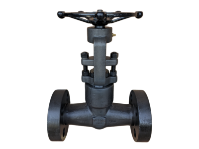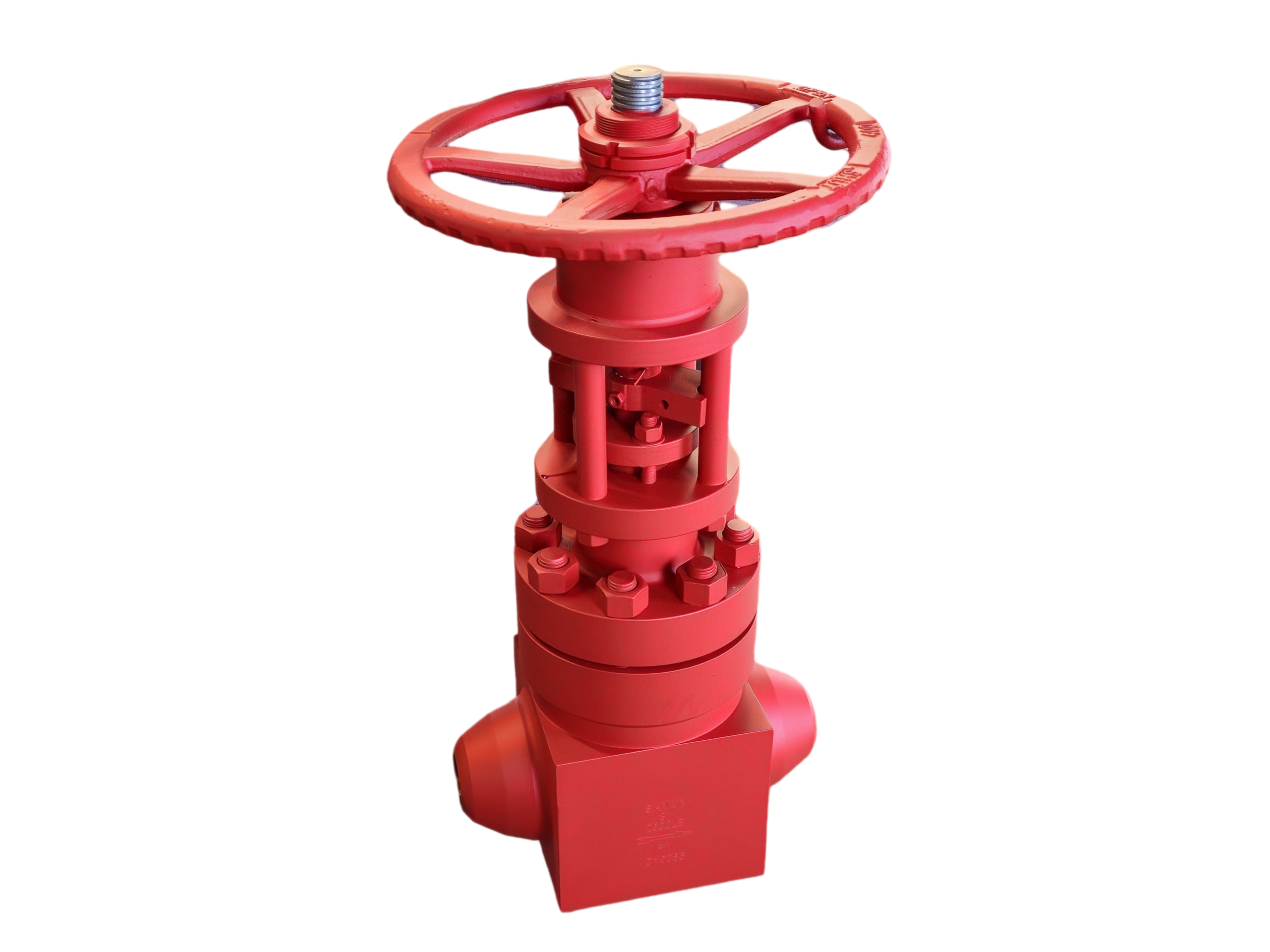
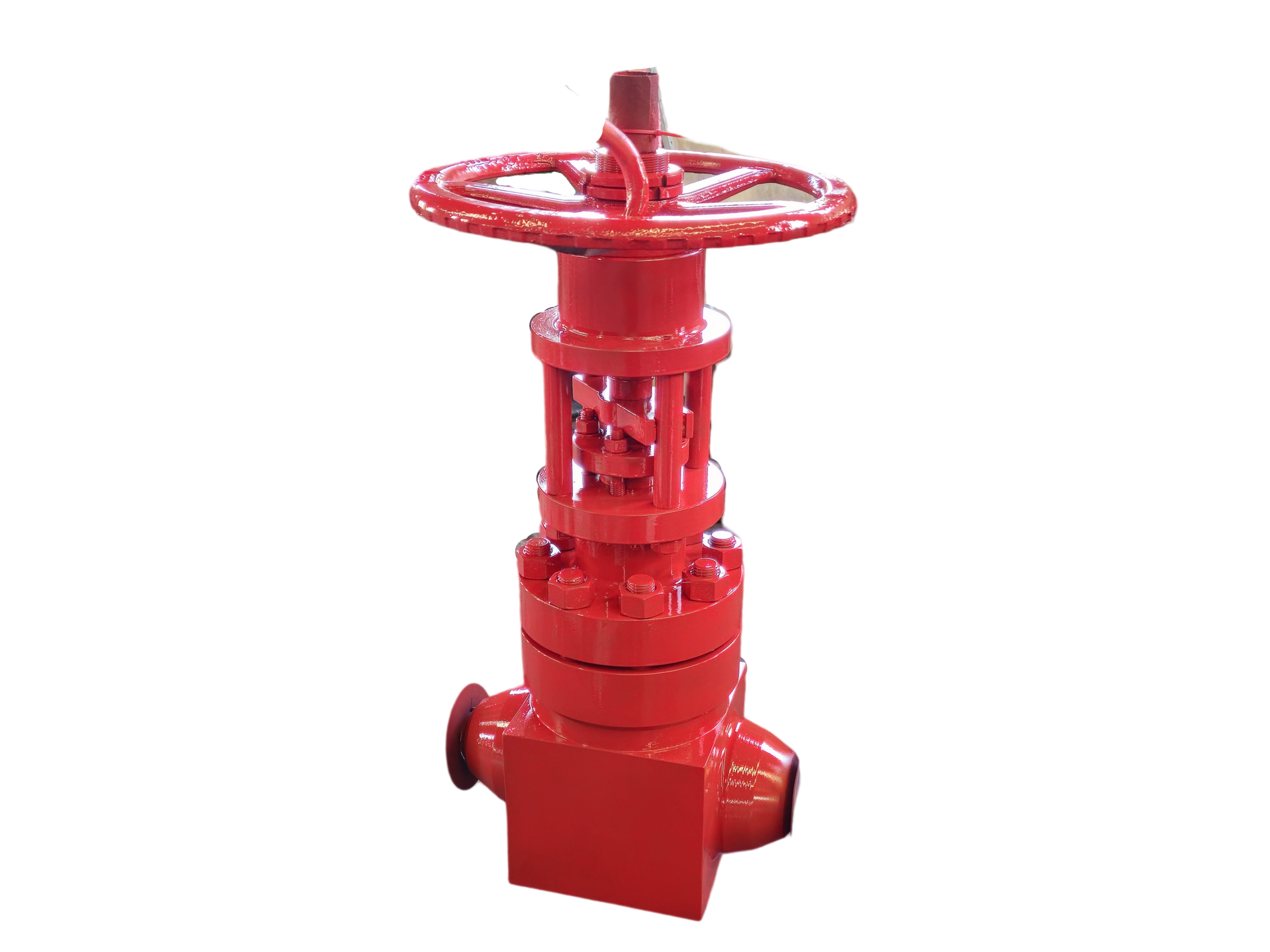
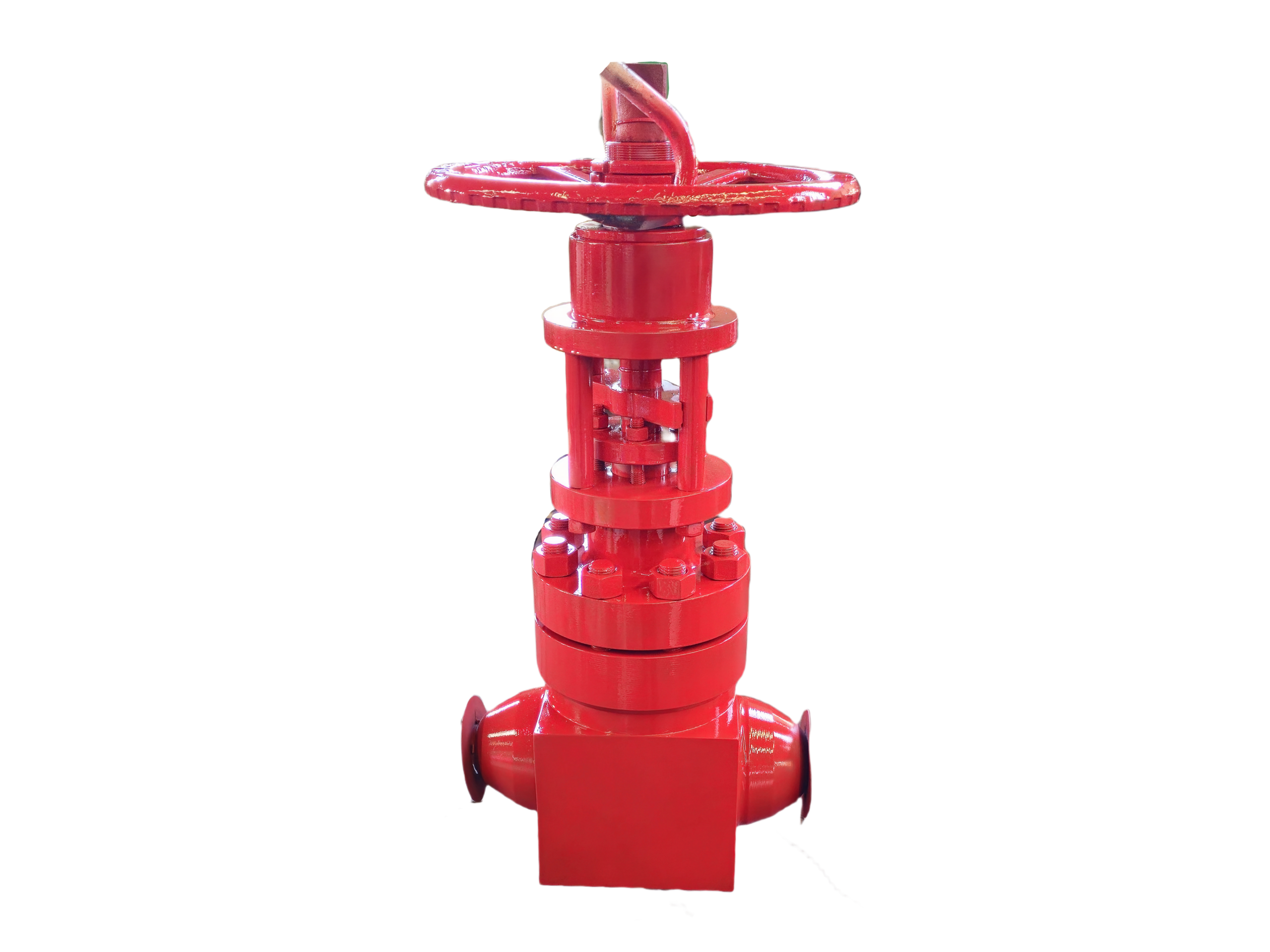
Globe Valve Open Die Forged— 3″ 2500LB BW
Description
Technical Data Sheet
Open Die Forged Globe Valve
Size & Class: 3″ 2500LB
End Connection: Butt-Weld (BW)
Body Material: ASTM A105N (Standard)
1. General Description
This is a high-pressure globe valve with the body and bonnet manufactured from open die forged ASTM A105N normalized carbon steel. The open die forging process provides exceptional grain flow and structural integrity, making it suitable for critical high-pressure applications. The valve features a rising stem, bolted bonnet, and Stellite hardfaced seating surfaces. It is designed for tight shutoff and flow regulation in steam, high-temperature water, oil, gas, and other high-pressure media. Butt-weld ends are prepared per ASME B16.25. The valve is operated by a handwheel and is actuator-ready with an ISO mounting pad if required.
2. Design Codes & Standards
Item Applicable Standard
Design & Manufacture API 602, BS 5352, ASME B16.34
Pressure-Temperature Rating ASME B16.34
Butt-Weld Ends ASME B16.25
Face-to-Face Dimensions ASME B16.10 (Long Pattern)
Inspection & Testing API 598
Forging Standard ASTM A105 / A105N
3. Main Technical Specifications
Nominal Size: 3″ (DN80)
Pressure Class: Class 2500 (2500LB)
End Connection: Butt-Weld (BW) per ASME B16.25
Body / Bonnet Material: ASTM A105N (Open Die Forged) – F22, F316, LF2, etc. available on request
Disc Material: A105 + Stellite 6 Overlay
Body Seat Face: Integral Stellite 6 Overlay
Stem Material: ASTM A276 410 (13Cr) or 17-4PH
Packing: Flexible Graphite with braided graphite end rings
Bonnet Gasket: 304+Graphite Spiral Wound
Bolting: A193 B7 / A194 2H
Operation: Handwheel (standard); gear operator or actuator mountable
Service Media: Steam, water, oil, gas, and general high-pressure fluids
Temperature Range: -29 °C to +425 °C (-20 °F to +800 °F)
4. Materials of Major Parts
No. Part Name Material Standard
1 Body A105N (Open Die Forged) ASTM A105
2 Bonnet A105N (Open Die Forged) ASTM A105
3 Disc A105 + STL.6 Overlay ASTM A105
4 Seat Integral STL.6 Overlay —
5 Stem A276 410 (13Cr) / 17-4PH ASTM A276
6 Packing Flexible Graphite —
7 Bonnet Gasket 304+Graphite Spiral Wound ASME B16.20
8 Stud A193 B7 ASTM A193
9 Nut A194 2H ASTM A194
10 Handwheel Carbon Steel (Zinc Plated) —
5. Principal Dimensions (3″ 2500LB BW)
Symbol Description Value (mm) Value (inch)
L Face-to-Face / End-to-End 473 18.62″
d BW End OD (for SCH XXS / 160) 88.9 3.50″
d1 BW End ID (approx., XXS) 58.4 2.30″
H (approx.) Centerline to Top of Handwheel ~620 ~24.4″
HW Dia. Handwheel Diameter ~400 ~15.7″
Weight Approx. Weight ~120 kg —
Weld Bevel Per ASME B16.25 Compound Bevel —
*Note: Face-to-face dimensions conform to ASME B16.10 Long Pattern for Class 2500. BW end dimensions are matched to pipe schedule (typically XXS or SCH 160). Final dimensions are subject to approved drawing.*
6. Performance Tests & Inspection
Shell Strength Test: 1.5 × Class 2500 rated pressure (approx. 622 bar / 9025 psi), water, hold time ≥1 minute, no leakage or permanent deformation.
High-Pressure Seat Test: 1.1 × rated pressure (approx. 456 bar / 6620 psi), water, zero leakage.
Low-Pressure Seat Test: 0.6 bar pneumatic, zero leakage.
Stem Operation: Smooth handwheel operation; disc lifts and seats without sticking.
Visual & Dimensional: 100% inspection for forging defects (cracks, laps); critical dimensions verified.
Material Certification: EN 10204 Type 3.1 available; PMI optional.
7. Installation & Maintenance Tips
Welding: Match the weld procedure to the forged A105N material. Preheat and post-weld heat treatment may be required per applicable welding codes. Keep the valve fully closed during welding to protect seating surfaces.
Flow Direction: Install per the arrow on the body (typically flow under the disc). Reverse installation compromises sealing and stem life.
Orientation: The stem should preferably be vertical. Horizontal installation is acceptable but may require additional yoke support for the actuator or gear.
High-Temperature Startup: After the first heat-up cycle, re-tighten the bonnet bolts and packing gland evenly to compensate for thermal expansion.
Packing: Periodically check for packing leakage. Retighten the gland evenly. For live-loading systems, follow manufacturer’s instructions for spring compression.
This technical data sheet is for selection reference only. The manufacturer reserves the right to change the design without prior notice. Final dimensions and materials are subject to the approved order-specific drawing.