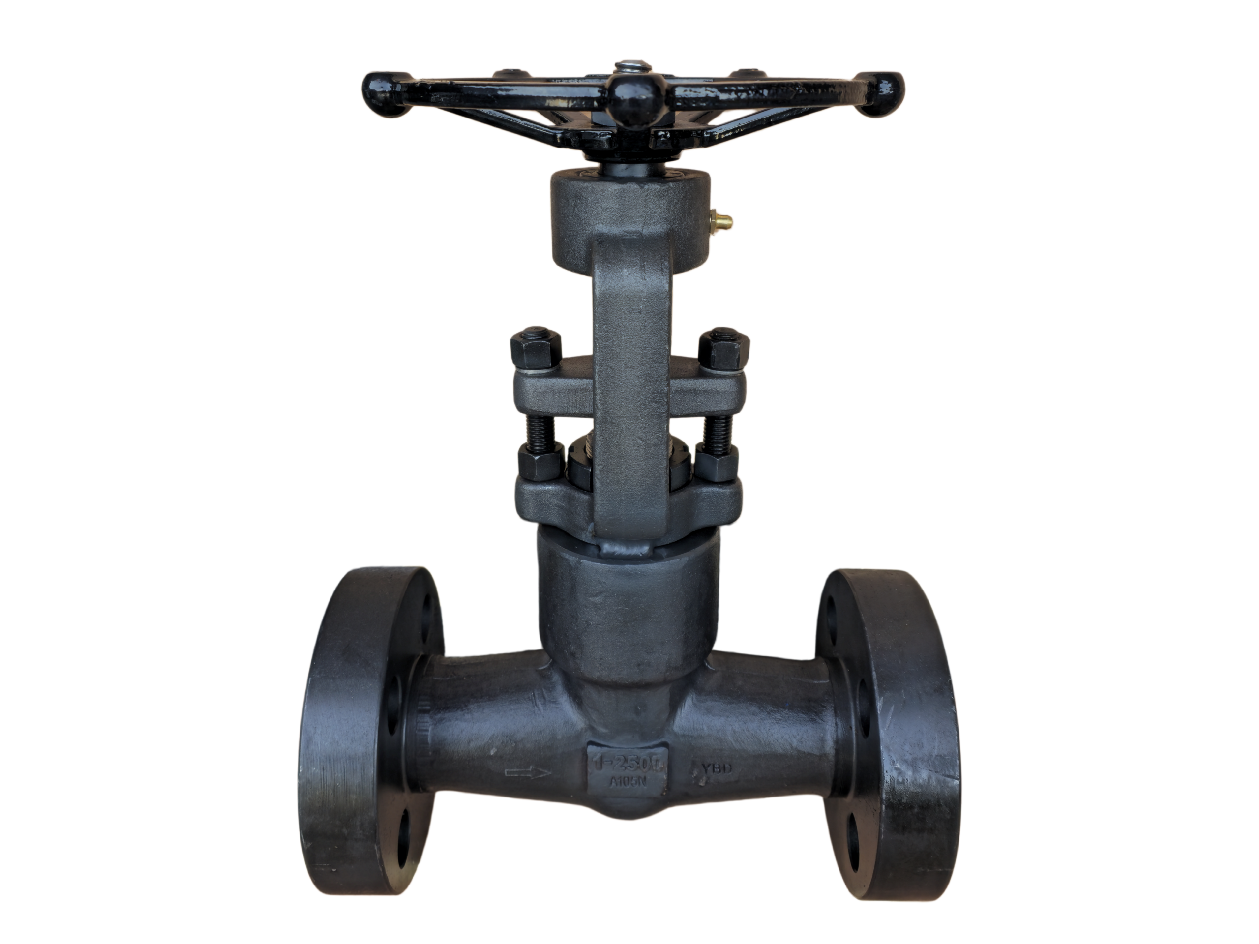
Globe Valve Closed Die Forged—1″ 2500LB RF
Description
Technical Data Sheet
Closed Die Forged Globe Valve
Size & Class: 1″ 2500LB RF
Body Material: ASTM A105N
1. General Description
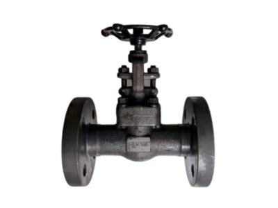
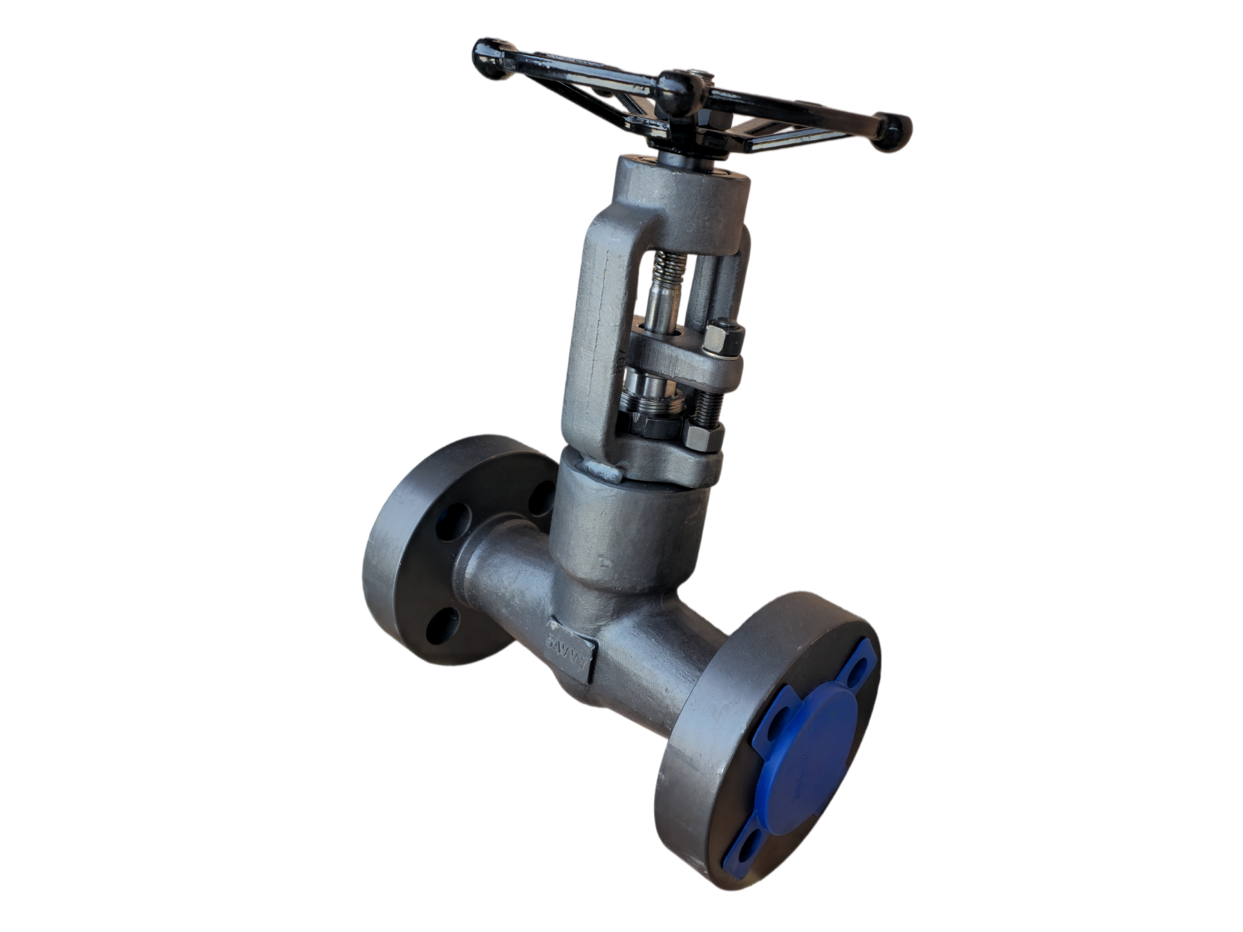
This is a high-pressure globe valve with a closed die forged, integral body and bonnet. Both body and bonnet are forged from ASTM A105N normalized carbon steel, offering dense grain structure and high strength. The valve features a rising stem and handwheel operation. Seating surfaces are overlayed with Stellite 6 hardfacing, providing exceptional resistance to erosion and wear. It is designed for flow regulation and tight shutoff under high-pressure conditions. Flanged ends comply with ASME B16.5 Raised Face (RF), Class 2500. The valve is widely used for high-temperature and high-pressure steam, water, oil, natural gas, and other general industrial media.
2. Design Codes & Standards
Item Applicable Standard
Design & Manufacture API 602, BS 5352, ASME B16.34
Pressure-Temperature Rating ASME B16.34
End Connections ASME B16.5 (RF)
Face-to-Face Dimensions ASME B16.10 (Long Pattern)
Inspection & Testing API 598
Forging Standard ASTM A105 / A105N
3. Main Technical Specifications
Nominal Size: 1″ (DN25)
Pressure Class: Class 2500 (2500LB)
Connection Type: Flanged RF
Body/Bonnet Material: ASTM A105N (Closed Die Forged)
Disc Material: A105 + Stellite 6 Overlay
Body Seat Face: Integral Stellite 6 Overlay
Stem Material: ASTM A276 410 (13Cr) or 17-4PH
Packing: Flexible Graphite
Gasket: 304+Graphite Spiral Wound / 316+Graphite
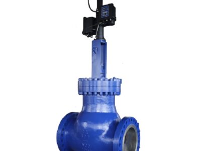
Operation: Handwheel (Standard); electric/pneumatic actuators available as an option
Service Media: Steam, water, oil, natural gas, etc.
Temperature Range: -29 °C to +425 °C (-20 °F to +800 °F)
4. Materials of Major Parts
No. Part Name Material Standard
1 Body A105N ASTM A105
2 Bonnet A105N ASTM A105
3 Disc A105 + STL.6 Overlay ASTM A105
4 Seat Integral STL.6 Overlay —
5 Stem A276 410 (13Cr) / 17-4PH ASTM A276
6 Packing Flexible Graphite —
7 Bonnet Gasket 304+Graphite Spiral Wound —
8 Stud A193 B7 ASTM A193
9 Nut A194 2H ASTM A194
10 Handwheel Malleable Iron / Carbon Steel —
5. Principal Dimensions (1″ 2500LB RF)
Symbol Description Value (mm) Value (inch)
L Face-to-Face Length 264 10.39″
D Flange Outer Diameter 159 6.25″
D1 Bolt Circle Diameter 108.0 4.25″
D2 Bolt Hole Diameter 22.2 0.88″
b Flange Min. Thickness (excl. RF) 28.6 1.12″
Flange Total Thickness (incl. RF) Approx. 35 Approx. 1.37″
H (approx.) Centerline to Top of Handwheel ~360 ~14.17″
HW Dia. Handwheel Diameter ~160 ~6.30″
Weight Approx. Weight ~15 kg —
Bolt Holes — 4 —
Bolt Size — 3/4″ UNC —
Note: Dimensions conform to ASME B16.10 and B16.5. The overall height is approximate. Final confirmed dimensions are subject to the approved drawing.
6. Performance Tests & Inspection
Shell Strength Test: 1.5 × Class 2500 rated pressure, hold time ≥1 minute, no visible leakage or permanent deformation.
Seat Tightness Test (High/Low Pressure): High-pressure test at 1.1 × rated pressure (water); low-pressure test at 0.6 bar pneumatic. Both meet API 598 zero leakage requirements.
Stem Operation: Handwheel operation is smooth, disc lifts and seats without sticking.
Visual & Dimensional Inspection: 100% visual inspection to ensure forging surfaces are free from defects such as cracks and laps. Critical dimensions are fully verified.
Material Certification (Optional): EN 10204 Type 3.1 material certificate and PMI spectral analysis available.
7. Installation & Maintenance Tips
The valve must be installed with the flow direction matching the arrow on the body, typically “flow under the seat” (low pressure under the disc). Reverse installation will damage the seating surface and affect operation.
The stem is recommended to be in a vertical upward position for ease of operation and packing maintenance.
Before initial high-temperature service, uniformly tighten bolts at ambient temperature. After reaching operating temperature, perform hot retightening of the bonnet bolts.
If abnormal resistance is encountered during handwheel operation, stop immediately and investigate the cause. Do not use extension handles or cheater bars to force operation.
Periodically check the stuffing box for leakage. If necessary, gently and evenly re-tighten the packing gland or replace the packing with the valve depressurized.
This technical data sheet is for selection reference only. The manufacturer reserves the right to change the design without prior notice. Final order shall be based on the approved drawing.