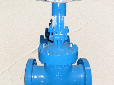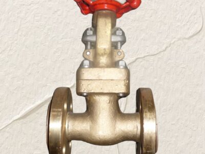
NRS Resilient Seated Gate Valve
Description
Technical Data Sheet
Product: Resilient Seated Non-Rising Stem (NRS) Gate Valve
Operation: Handwheel Operated or Square Key Adapter Operated
Typical Standard: BS 5163 / EN 1171 / AWWA C515
1. General Description
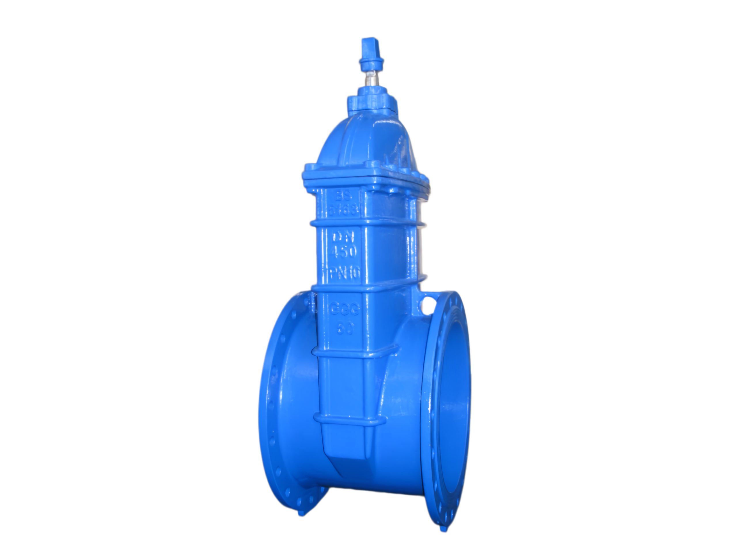
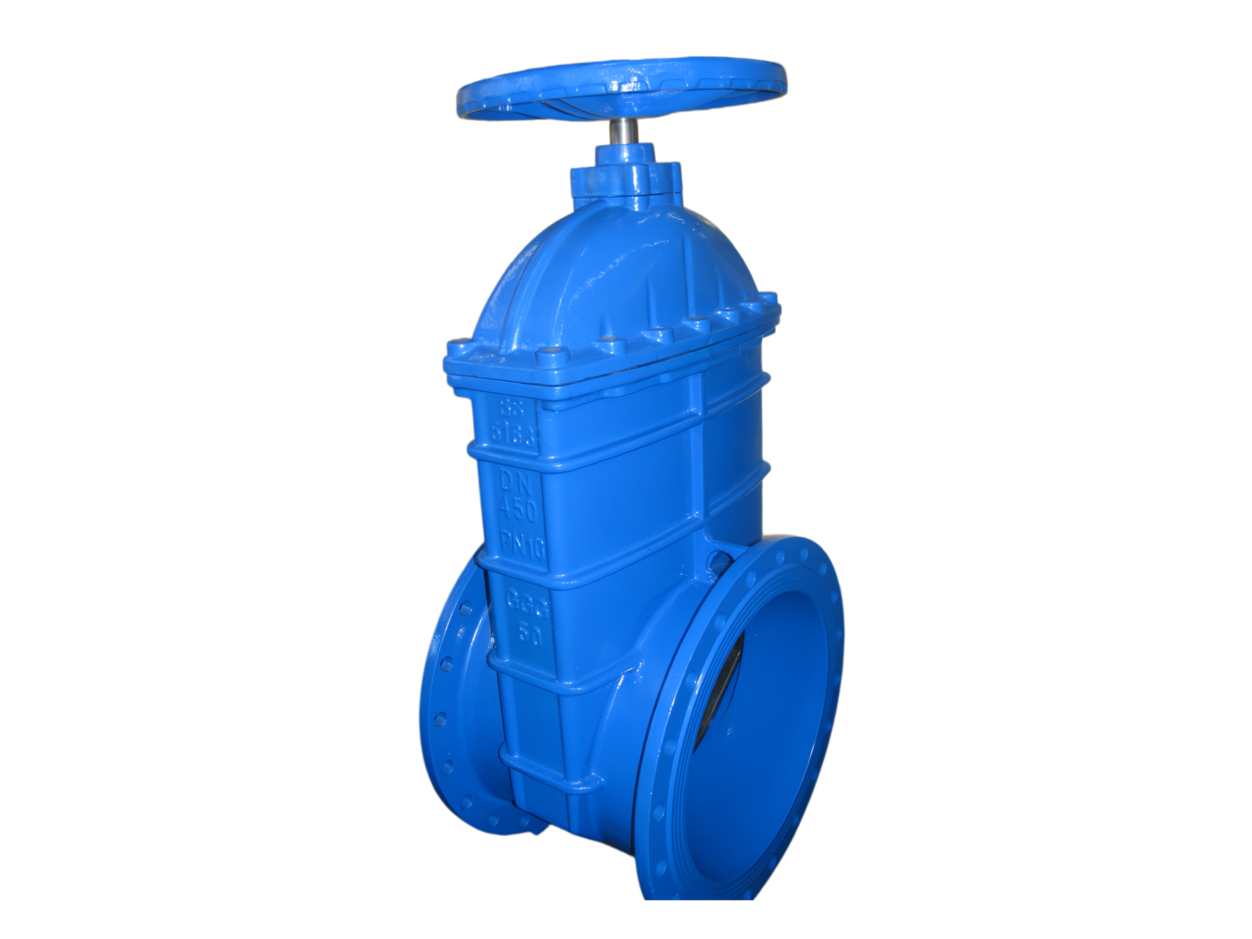
This resilient seated gate valve features a non-rising stem design with a full-bore, smooth passage to minimize pressure loss and prevent debris accumulation. The disc is fully encapsulated in EPDM or NBR rubber, providing bubble-tight shutoff without the need for wedge seating or pocket fouling. The valve is operated via a handwheel for above-ground applications or a square key adapter (cap) for buried service actuated with a T-key. The fusion-bonded epoxy (FBE) coating inside and out ensures excellent corrosion protection, and the O-ring stem seal design eliminates the need for routine packing adjustment.
2. Design, Manufacturing & Inspection Standards
-
Design & Manufacture: BS 5163 (Resilient-Seated Gate Valves for Waterworks) / EN 1171 / AWWA C515
-
Pressure Rating: PN10, PN16 or Class 125 (200 psi) – This sheet uses PN16 as standard
-
Flange Drilling: BS EN 1092-2 PN16 (other standards on request)
-
Face-to-Face: BS 5163 Short Pattern (Series according to standard)
-
Inspection & Testing: BS EN 12266-1 (Shell & Seat tightness), Rate A (zero leakage)
-
Coating: GSK-approved FBE, minimum 250 μm, to AWWA C550 or WRAS requirements
-
Suitable Media: Potable water, raw water, wastewater, and neutral liquids
3. Technical Parameters
| Parameter | Description |
|---|---|
| Nominal Size | DN50 – DN600 (2″ – 24″) |
| Pressure Class | PN10 / PN16 (16 bar max working pressure) |
| Body & Bonnet Material | Ductile Iron ASTM A536 Gr. 65-45-12 / GJS-500-7 |
| Disc Material | Ductile Iron core, fully encapsulated with resilient EPDM / NBR |
| Stem Type | Non-Rising Stem (NRS), Stainless Steel SS420 or SS316 |
| Stem Nut | Dezincification-resistant brass (CW617N) or bronze |
| Stem Seal | EPDM / NBR O-rings, maintenance-free (no packing gland) |
| Bonnet Bolting | Stainless Steel SS304 or SS316, recessed & sealed |
| Operation Type | ① Handwheel (spoked or solid, Ductile Iron) – above ground ② Square Key Adapter (2″ square cap, Ductile Iron) – buried service |
| Closing Direction | Clockwise to close (standard); Counterclockwise available |
| Coating | Fusion-Bonded Epoxy (FBE) blue/black, WRAS approved for potable water |
| Media Temperature (EPDM) | 0°C to +80°C (32°F to 176°F) continuous |
| Media Temperature (NBR) | 0°C to +80°C, can handle oily water (confirm resistance) |
4. Materials of Main Parts
| No. | Part Name | Material |
|---|---|---|
| 1 | Body | Ductile Iron GJS-500-7 (ASTM A536 65-45-12) |
| 2 | Bonnet | Ductile Iron (same as body) |
| 3 | Disc (Wedge) | Ductile Iron fully vulcanized with EPDM / NBR rubber |
| 4 | Stem (NRS) | Stainless Steel SS420 / SS316 |
| 5 | Stem Nut | Brass CW617N or Bronze C84400 |
| 6 | O-Rings (Stem/Thrust) | EPDM (NBR optional) |
| 7 | Thrust Washer | PTFE / Bronze-backed PTFE |
| 8 | Bonnet Gasket | EPDM |
| 9 | Bonnet Bolts & Washers | Stainless Steel SS304/SS316, encapsulated |
| 10a | Handwheel (above-ground) | Ductile Iron / Spheroidal Graphite Iron |
| 10b | Key Adapter Cap (buried) | Ductile Iron with 2″ square socket |
| 11 | Dust Cover / Indicator Cap | Plastic or Ductile Iron |
5. Main Dimensions and Weights
a) Handwheel Operated (PN16, BS 5163 Short Pattern)
| DN | L (mm) | H (mm) (Approx. open) | Handwheel Ø (mm) | Weight (kg) |
|---|---|---|---|---|
| 50 | 150 | 310 | 160 | 9 |
| 65 | 170 | 340 | 180 | 12 |
| 80 | 180 | 375 | 200 | 15 |
| 100 | 190 | 430 | 220 | 20 |
| 125 | 200 | 485 | 250 | 27 |
| 150 | 210 | 550 | 300 | 36 |
| 200 | 230 | 685 | 350 | 58 |
| 250 | 250 | 810 | 400 | 85 |
| 300 | 270 | 935 | 450 | 120 |
| 400 | 310 | 1150 | 560 | 220 |
b) Square Key Adapter Operated (PN16, Buried Service)
Height measured from pipe center to top of square cap.
| DN | L (mm) | H (mm) (top of 2″ sq. cap) | Square Cap Size | Weight (kg) |
|---|---|---|---|---|
| 50 | 150 | 205 | 2″ | 8 |
| 80 | 180 | 250 | 2″ | 14 |
| 100 | 190 | 285 | 2″ | 19 |
| 150 | 210 | 355 | 2″ | 35 |
| 200 | 230 | 430 | 2″ | 57 |
| 250 | 250 | 500 | 2″ | 84 |
| 300 | 270 | 570 | 2″ | 118 |
| 400 | 310 | 710 | 2″ | 218 |
Note: All dimensions and weights are typical. Final certified drawings will confirm exact values. Extended key adapters/extension spindles can be supplied on request.
6. Pressure-Temperature Ratings
| Temperature (°C) | Maximum Working Pressure (bar) |
|---|---|
| -10 to 50 | 16.0 |
| 60 | 15.0 |
| 80 | 14.0 |
Test Pressures (Ambient)
Shell Test (1.5 × PN): 24.0 bar
Seat Test (1.1 × PN): 17.6 bar – Zero leakage allowed
7. Installation and Maintenance Notes
-
Orientation: Install with stem vertically upward. Horizontal installation is acceptable with stem within ±45° of vertical.
-
Buried Service: For key adapter versions, install a surface box over the adapter to allow T-key access from grade. Ensure no side loads are transmitted from backfill.
-
Handwheel: Do not use cheater bars; a geared actuator is recommended for sizes ≥DN250 or when frequent operation is required.
-
Maintenance: The O-ring stem seal requires no routine adjustment. The valve is maintenance-free for its service life under normal conditions. If leakage occurs at the stem, the thrust cartridge/O-ring can be replaced with the valve in the partially open position (line depressurized).
-
Flushing: Fully open the valve before pipeline flushing to prevent debris from damaging the resilient seat.
8. Ordering Information
Please specify the following:
-
Nominal size and pressure class (e.g., DN150 PN16)
-
Body/Disc material (standard: Ductile Iron / EPDM encapsulated disc)
-
Operation type: Handwheel or Square Key Adapter (indicate 2″ or other square size)
-
Closing direction: Clockwise close (standard) or Counterclockwise close
-
Extension requirements: Valve box extension spindle length (from pipe center to grade)
-
Special coatings or certifications (WRAS, NSF61, ACS, etc.)
-
Media type and operating temperature