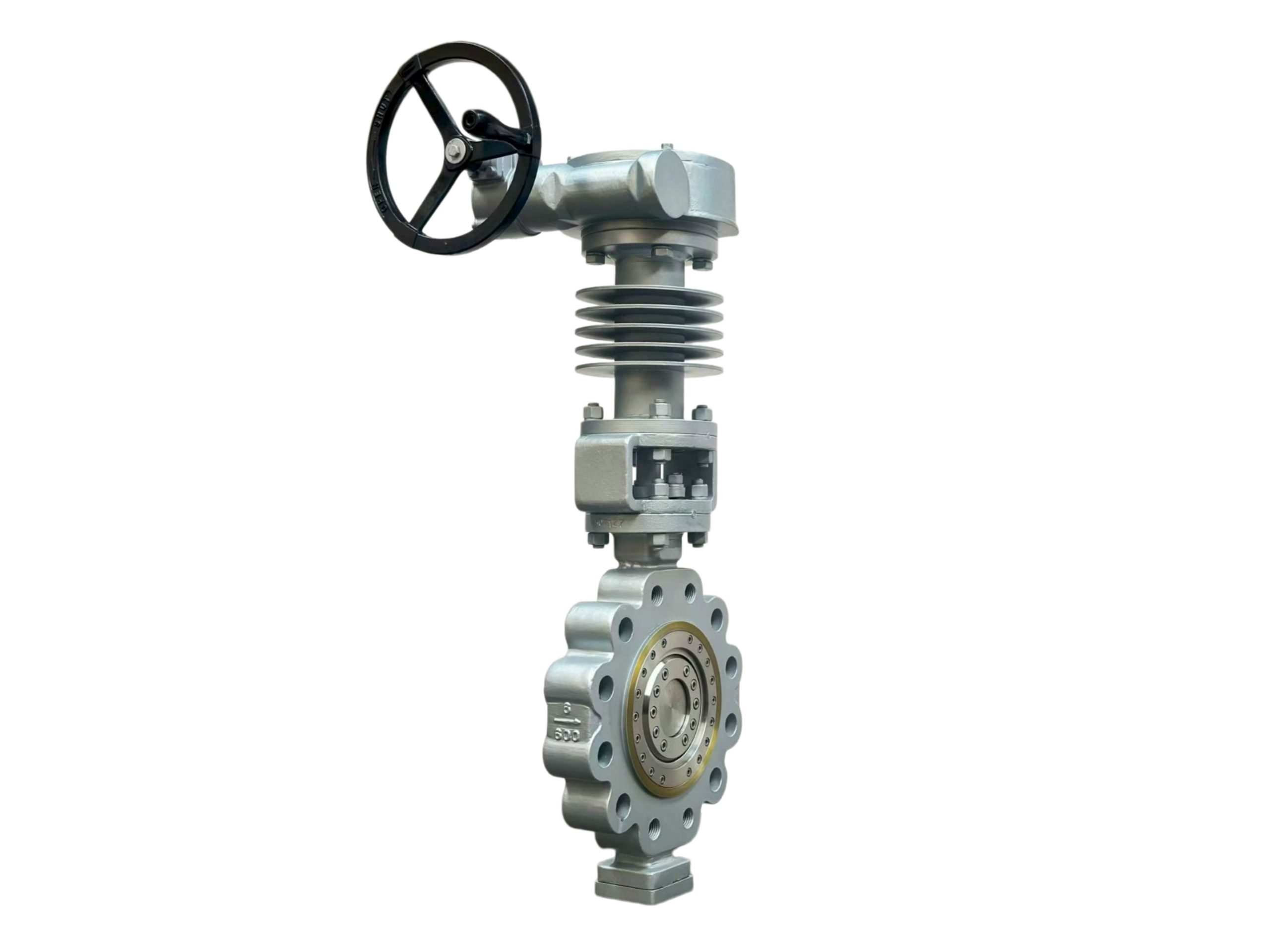
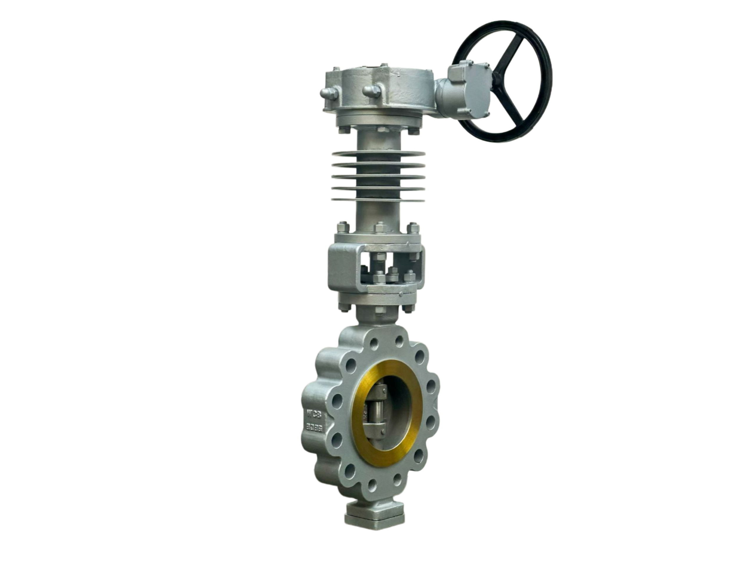
HT-HP Triple Offset Butterfly Valves—6″ 600LB LUG
Description
Technical Data Sheet
HT-HP Triple Offset Butterfly Valve
Size: 6″ (DN150)
Pressure Class: 600LB
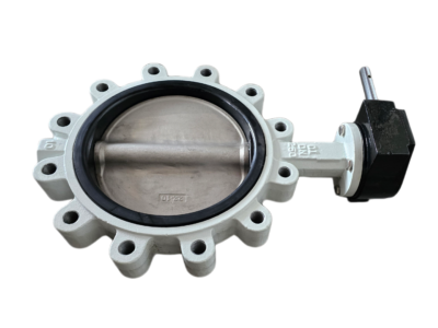
Body Type: LUG (Threaded Inserts)
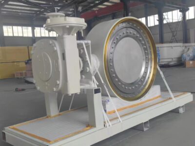
Design Feature: Cooling Fins (Heat Dissipation Extension)
1. General Description
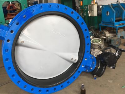
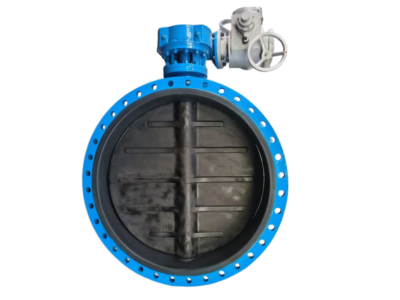
This is a high-performance, high-temperature, high-pressure (HT-HP) triple offset butterfly valve with a cast body and a lug-style connection. The triple offset design (three eccentricities) ensures a friction-free, cam-action seating with zero leakage metal-to-metal sealing. The valve is specifically designed for demanding applications in refining, petrochemical, power generation, and offshore platforms, handling steam, thermal oils, hydrocarbons, and high-temperature gases. The integrated cooling fin extension on the bonnet effectively dissipates heat, protecting the packing, actuator, and gear operator, and allowing service temperatures up to +600 °C (+1112 °F) depending on material. It is fire-safe certified, has blow-out proof stem, and can be supplied with manual gear, pneumatic, or electric actuation.
2. Design Codes & Standards
Item Applicable Standard
Design & Manufacture API 609 (Category B), ASME B16.34, EN 593
Pressure-Temperature Rating ASME B16.34
Face-to-Face Dimensions API 609 / ISO 5752 Series 20 (Short) or Series 14 (Long) – project specific
Flange Compatibility (LUG) ASME B16.5 / ASME B16.47 (flange drilling & threading)
Inspection & Testing API 598, ISO 5208 (Zero Leakage, Rate A)
Fire-Safe Design API 607 / ISO 10497 (Fire tested by design)
Fugitive Emissions (Optional) ISO 15848-1
Casting Standard ASTM A217, A351, etc.
3. Main Technical Specifications
Nominal Size: 6″ (DN150)
Pressure Class: 600LB (ASME B16.34, PN100 equivalent for reference)
Body Type: Lug (tapped holes for mounting between flanges and dead-end service capability)
Body Material (Cast):
Standard HT: ASTM A217 WC6 (1.25Cr-0.5Mo) – up to ~540°C
Higher HT: ASTM A217 WC9 (2.25Cr-1Mo) – up to ~600°C
Stainless HT: ASTM A351 CF8M (316) – up to ~600°C for corrosive service
Others: A351 CF8C, A890 Duplex, etc. on request
Disc Material: ASTM A217 WC6/WC9 + Stellite 6 seating edge, or CF8M + Stellite, or solid Duplex.
Seat Ring: Laminated graphite/PTFE combination for fire-safe, or solid Inconel/Stellite weld overlay for all-metal seating.
Seat Design: Triple offset geometry; torque-seated metal-to-metal (with optional graphite laminate insert for bidirectional zero leakage).
Stem Material: 17-4PH (A564), Inconel 718, or A479 XM-19 depending on temperature.
Packing: Flexible graphite (fire-safe, high-temperature), with live-loading option.
Extension Bonnet: Extended with integral cooling fins; height designed to keep packing area temperature below 100°C at maximum service temperature.
Operation: Gear operator (standard for 6″), ISO 5211 top flange for pneumatic/electric/hydraulic actuators. Locking device optional.
Temperature Range: -29 °C to +600 °C depending on body/disc material selection.
Leakage Class: Zero leakage (API 598), Rate A per ISO 5208.
4. Materials of Major Parts (Typical WC6 Construction)
No. Part Name Material (Standard) Standard
1 Body ASTM A217 WC6 (Cast) ASTM A217
2 Disc ASTM A217 WC6 + Stellite 6 Edge ASTM A217
3 Seat Ring (Laminated) Graphite + SS316L —
4 Stem (One-piece or Two-piece) ASTM A564 17-4PH / Inconel 718 ASTM A564
5 Packing Flexible Graphite —
6 Extension Bonnet with Cooling Fins ASTM A216 WCB / A217 WC6 ASTM A216/A217
7 Bearing SS316 + PTFE / Graphite —
8 Gear Operator Ductile Iron / Carbon Steel, Epoxy Painted —
9 Bolting (Body/Lug inserts) A193 B7/B16, A194 2H/7 ASTM A193
10 Gland Follower / Bolts SS304 / A193 B8 —
Note: The laminated seat ring provides both high-temperature capability and fire-safe back-up. For pure metal-to-metal (Inconel seat), zero leakage is achieved by torque seating.
5. Principal Dimensions (6″ 600LB LUG, Typical)
Symbol Description Value (mm) Value (inch)
L Face-to-Face (per API 609 Short) 114 4.49″
D Lug Flange Outer Diameter 355 14.00″ (approx.)
D1 Bolt Circle Diameter 292 11.50″
D2 Bolt Hole / Thread Size M33 / 1-1/4″ UNC —
H1 Centerline to Top of Gear Operator Pad ~450 ~17.7″
H2 Centerline to Top of Cooling Fins (bonnet height) ~350 ~13.8″
ISO Pad Actuator Mounting (standard) F12 / F14 —
Cv Approx. Flow Coefficient (full open 90°) ~1100 —
Weight Approx. Weight (incl. gear & fins) ~75 kg —
Number of Lugs (Typically threaded through) 8 —
*Note: Dimensions are based on ASME B16.5 flange compatible lugs and API 609 short pattern. Face-to-face can also be long pattern (L=178 mm) for some applications. The exact dimension is as per the final approved drawing. Flange bolt holes are tapped threads for studs.*
6. Performance Tests & Inspection
Shell Strength Test: 1.5 × Class 600 rated pressure (approx. 153 bar / 2220 psi), water, hold time ≥1 minute, no leakage.
Seat Tightness Test (High Pressure): 1.1 × rated pressure (approx. 112 bar / 1625 psi), water, zero leakage.
Low-Pressure Seat Test: 0.6 bar pneumatic, zero leakage.
Fire-Safe Test: Fire test per API 607 / ISO 10497; the graphite laminate seal ensures leak-tightness before, during, and after burn.
Torque/Operation: Full stroke at no load, max torque verified. No sticking or excessive torque.
Cooling Fin Verification: Temperature mapping on bonnet/fin assembly under design temperature.
Material & NDE: Dye penetrant (PT) on casting, positive material identification (PMI). EN 10204 Type 3.1 certification.
7. Installation & Maintenance Tips
Lug Mounting: The valve can be installed between two flanges (wafer style) or at the end of a line (dead-end service) with a blind flange on the downstream side. Ensure the flange bolts are fully threaded into the tapped lugs and torqued evenly.
Orientation: The stem should preferably be horizontal for high-temperature service, but vertical with cooling fins is also acceptable. Ensure adequate clearance around the cooling fins for air circulation. Never insulate the fin area.
High-Temperature Startup: After the initial heat-up cycle, re-torque the packing gland bolts and bonnet-to-body bolts (if any) to compensate for thermal expansion.
Operation: Do not exceed the maximum allowable stem torque. The triple offset valve requires a torque-seating mechanism (gear box or actuator) that provides a mechanical advantage to seat the metal seal.
Fire-Safe Maintenance: If the valve experiences a fire, the graphite laminate seat may need replacement. The metal parts should be inspected for hardness and distortion.
Packing: Regular inspection of the stuffing box is recommended. Graphite packing requires no lubrication. Live-loading can be added for fugitive emission control.
This technical data sheet is for general selection and design reference. The manufacturer reserves the right to change dimensions, materials, and design details without prior notice. All final specifications shall be documented in the approved order-specific datasheet and assembly drawing.