Cartridge Rubber Seat Lugged Butterfly Valves
Description
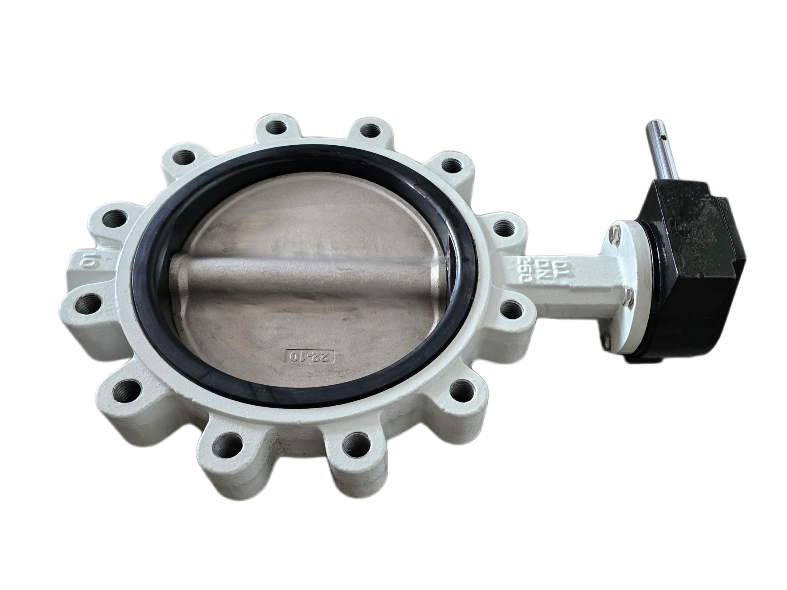
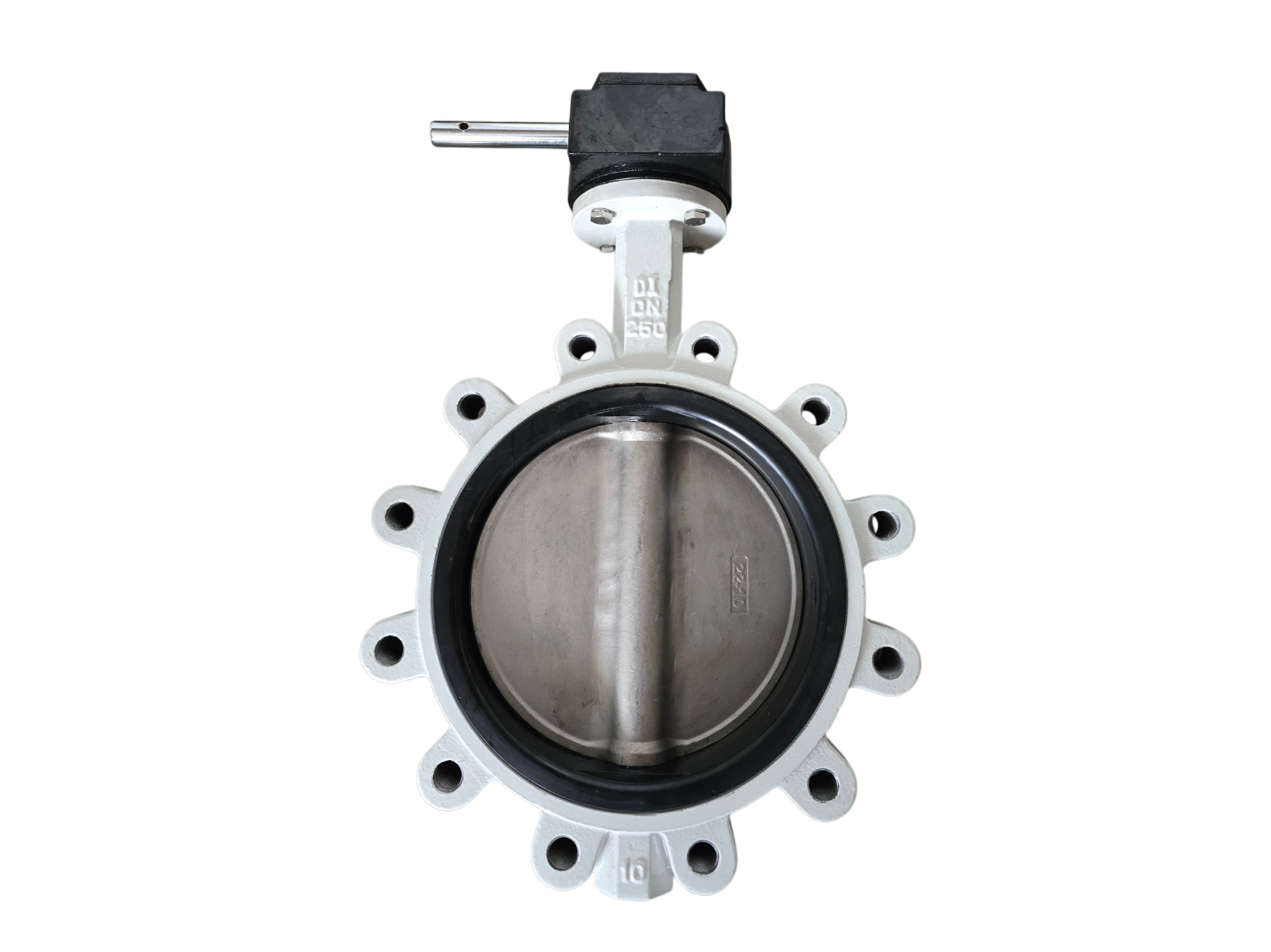
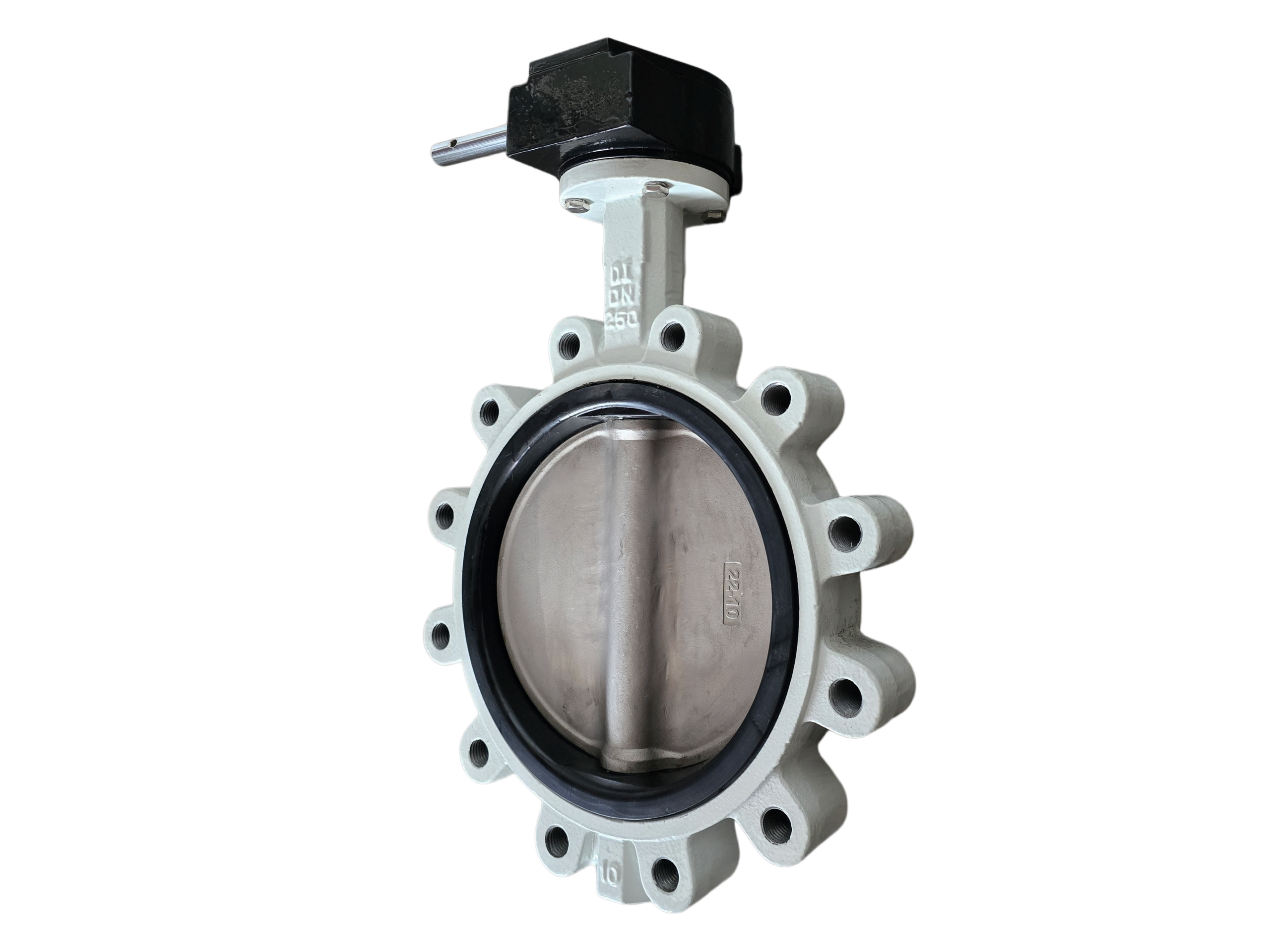
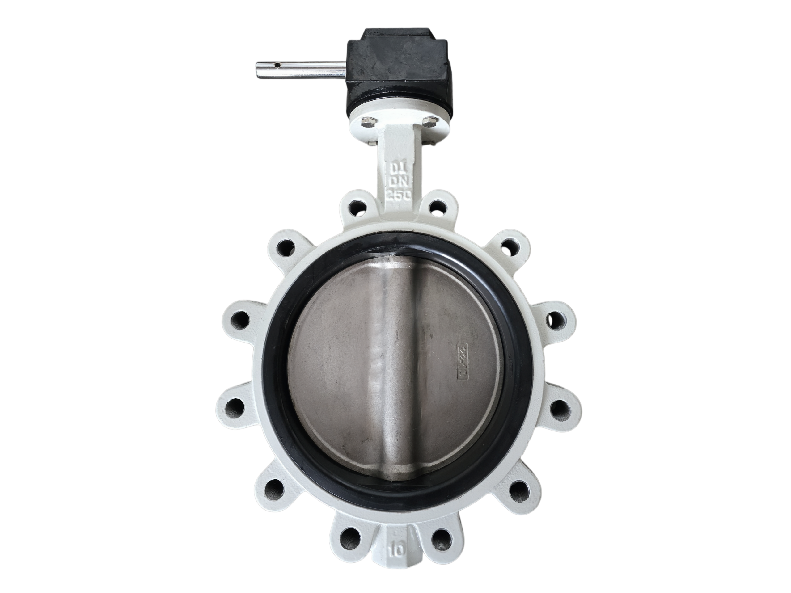
Cartridge Rubber Seat Lugged Butterfly Valve
Technical Data Sheet
1. Product Overview
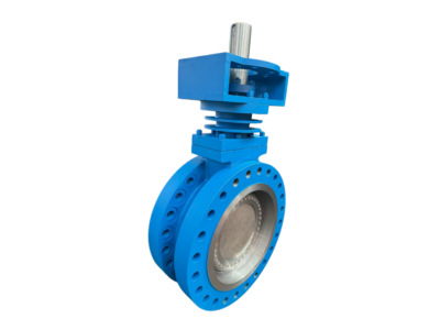
The Cartridge Rubber Seat Lugged Butterfly Valve combines the benefits of a replaceable, fully rubber-lined cartridge seat with a lugged body design. The single-piece rubber seat completely isolates the media from the body, ensuring superior corrosion resistance and allowing on-site seat replacement without removing the disc or stem. The lugged connection features threaded inserts on the body flange, enabling single-side pipe disassembly and dead-end service capability. This design is ideal for water supply, HVAC, water treatment, chemical processing, power plants, and marine systems where maintenance flexibility and pipeline independence are essential.
2. Design Features & Benefits
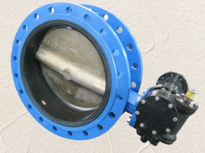
Lugged Body Design: Threaded lugs (or through-hole options) permit downstream pipe removal without affecting the upstream line, and allow the valve to be used as an end-of-line valve.
Replaceable Cartridge Seat: Single-piece rubber liner allows for quick, in-line replacement without special tools.
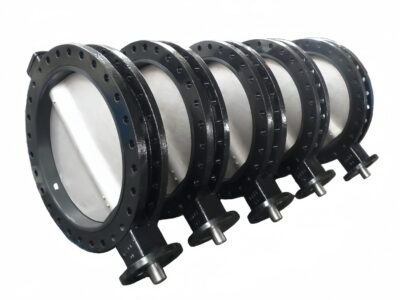
Full Liner Encapsulation: The rubber seat completely encapsulates the body flow passage, preventing any media contact with the metal body.
Bidirectional Zero Leakage: Pre-compressed seat lip design ensures bubble-tight shut-off in both directions under low and high pressure.
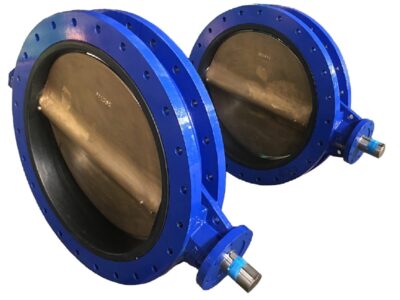
Streamlined Disc: Pinless or streamlined pin connection design, offering low flow resistance and high flow capacity (Cv).
Integrated Stem Seals: Multiple O-ring seals on the upper and lower stem combined with self-lubricating bearings for maintenance-free operation.
ISO 5211 Top Flange: Standardized mounting interface for direct connection of handles, gearboxes, electric, and pneumatic actuators.
Modular Design: High interchangeability of body, seat, disc, and shaft components reduces spare parts inventory.
3. Technical Parameters
Item Specification Range
Nominal Diameter (DN) DN50 – DN600 (2″ – 24″)
Pressure Rating PN6 / PN10 / PN16 (Class 150)
Connection Type Lugged (Threaded Inserts / Through-Hole)
Operating Temperature Range -4°F to 266°F (-20°C to 130°C), depending on seat material and pressure
Seat Material EPDM, NBR, FPM (Viton®), Silicone, White/Food Grade EPDM
Body Material Ductile Iron GGG40/50 (DI); Optional: Cast Iron, Cast Steel/Stainless Steel
Disc Material CF8M (SS316), CF8 (SS304), Duplex Stainless Steel, DI+Nylon 11 Coated, Aluminum Bronze
Stem Material SS420, SS431, SS316, Monel
Applicable Media Fresh water, wastewater, seawater, weak acids/alkalis, oils, compressed air, slurries, food fluids (depending on seat material)
Operation Lever Handle (DN50–DN150), Gearbox (DN200+), Electric Actuator, Pneumatic Actuator
Coating Epoxy powder coating, ≥250μm, standard color RAL 5015 Blue
4. Seat Material Operating Conditions
Seat Material Abbreviation Temperature Range Typical Media
Ethylene Propylene Diene Monomer EPDM -4°F ~ 248°F (-20°C ~ 120°C) Hot/cold water, steam condensate, acids, alkalis, alcohols, ketones
Nitrile Butadiene Rubber NBR 14°F ~ 176°F (-10°C ~ 80°C) Oils, hydraulic fluids, aliphatic hydrocarbons, water
Fluoroelastomer FPM (Viton®) 14°F ~ 302°F (-10°C ~ 150°C) Hot oils, solvents, strong acids, chemical media
Silicone Rubber VMQ -40°F ~ 356°F (-40°C ~ 180°C) Food products, hot air, low-concentration chemicals
Food Grade EPDM W-EPDM -4°F ~ 248°F (-20°C ~ 120°C) Drinking water, food, beverages
5. Bill of Materials
No. Component Standard Material Optional Material
1 Body (Lugged) Ductile Iron GGG50 / 65-45-12 Cast Iron HT250, Cast Steel WCB, SS304/316
2 Disc SS316 (CF8M) SS304, DI+Nylon11, Aluminum Bronze, Duplex Steel
3 Cartridge Seat EPDM NBR, FPM, Silicone, W-EPDM
4 Stem SS420 SS316, SS431, Monel
5 Upper Bearing PTFE + Bronze Backed Stainless Steel PTFE Composite
6 Lower Bearing PTFE Composite Same as above
7 O-Rings EPDM / NBR FPM
8 Retaining Ring / Gland Stainless Steel
9 Handle/Gearbox Aluminum Alloy / Ductile Iron Custom actuator interface
6. Applicable Standards
Item Standard
Design & Manufacturing API 609, EN 593, MSS SP-67, BS 5155
Face-to-Face Dimension EN 558-1 Series 16, API 609 Category A (Lugged), ISO 5752
Lug Drilling EN 1092-2 PN10/PN16, ASME B16.5 Class 150, AS 2129 Table E
Top Flange ISO 5211
Pressure Testing API 598, ISO 5208 (Rate A – Zero Leakage)
Coating Conforms to WIS 4-52-01, GSK Standards
7. Dimensions & Weights (Example for PN16 Lugged Configuration)
DN (mm) Inch L (mm) H1 (mm) H2 (mm) Bolt Circle Dia. (mm) Lug Qty. & Thread Actuator Flange ISO 5211 Approx. Weight (kg)
50 2″ 46 85 170 125 4-M16 F05 3.0
65 2.5″ 46 95 185 145 4-M16 F05 3.8
80 3″ 46 105 195 160 8-M16 F05 4.5
100 4″ 52 118 215 180 8-M16 F07 6.0
125 5″ 56 130 235 210 8-M16 F07 8.0
150 6″ 56 145 260 240 8-M20 F07 10.5
200 8″ 60 170 310 295 8-M20 F10 16.0
250 10″ 68 195 355 350 12-M20 F10 25.0
300 12″ 78 225 405 400 12-M20 F12 34.0
350 14″ 78 255 460 460 16-M20 F12 50.0
400 16″ 114 290 530 515 16-M24 F14 72.0
500 20″ 127 350 630 620 20-M24 F16 115.0
600 24″ 154 410 735 725 20-M27 F16 175.0
*Note: L – Face-to-face dimension according to EN 558-1 Series 16. H1 – Centerline to top of stem height; H2 – Maximum disc height in fully open position. Lug drilling can be supplied to match EN 1092-2 PN16 as standard; other drilling patterns available upon request. Weights are approximate.*
8. Pressure-Temperature Ratings (for EPDM Seat / Ductile Iron Body)
Temperature (°F) -4 ~ 122 176 212 248
Temperature (°C) -20 ~ 50 80 100 120
Max. Operating Pressure (bar) 16.0 14.0 12.0 10.0
For other seat materials and body combinations, please refer to the corresponding EN or ASME pressure-temperature curves.
9. Installation & Maintenance Instructions
Installation Notes
Lugged valves can be installed as end-of-line service valves; ensure the pipeline is designed to handle the pressure and mechanical loads when one side is disconnected.
Before installation, confirm that the pipe flange inner diameter allows the disc to fully open. The disc should be in a slightly open position (approx. 10°).
Tighten the lug bolts gradually in a diagonal pattern to the recommended torque. When used in dead-end service, ensure the appropriate bolt material and sealing gasket are used for the blind end.
Before replacing the cartridge seat, the pipeline must be drained and depressurized.
Cartridge Seat Replacement Procedure
Close and lock out the pipeline. Disconnect actuator power or air supply.
Remove the bolts from the lugs connecting the valve to the pipe flanges. The lugged design allows the valve to remain secured on one side while the other is dismantled. Remove the valve from the pipeline. The disc and stem do not need to be disassembled.
Carefully pry out the old rubber seat from the body edge using a flat-head screwdriver or a specialized pry tool.
Clean the body cavity and apply a small amount of neutral lubricant.
Evenly press the new seat into the body flow path, ensuring the lip edges are completely embedded.
Reinstall the valve, tighten lug bolts to specification, and commission.
10. Ordering Information
To ensure fast and accurate selection, please provide the following:
Valve Model / Series
Nominal Diameter (DN) and Pressure Rating (PN/Class)
Connection Type (Lugged)
Body Material
Disc Material
Seat Material (EPDM/NBR/FPM…)
Operation Type (Lever/Gearbox/Electric/Pneumatic) and actuator specifications
Media Type and Working Temperature
Flange Drilling Standard (EN 1092-2 / ASME B16.5 / AS 2129)
Special coating or certification requirements (e.g., drinking water approvals WRAS, KTW, ACS)
Ordering Example: CSW-BFV-L-150-DI-316-EPDM-LEV specifies a Cartridge Lugged Butterfly Valve, DN150, Ductile Iron body, Stainless Steel 316 disc, EPDM seat, with lever handle.