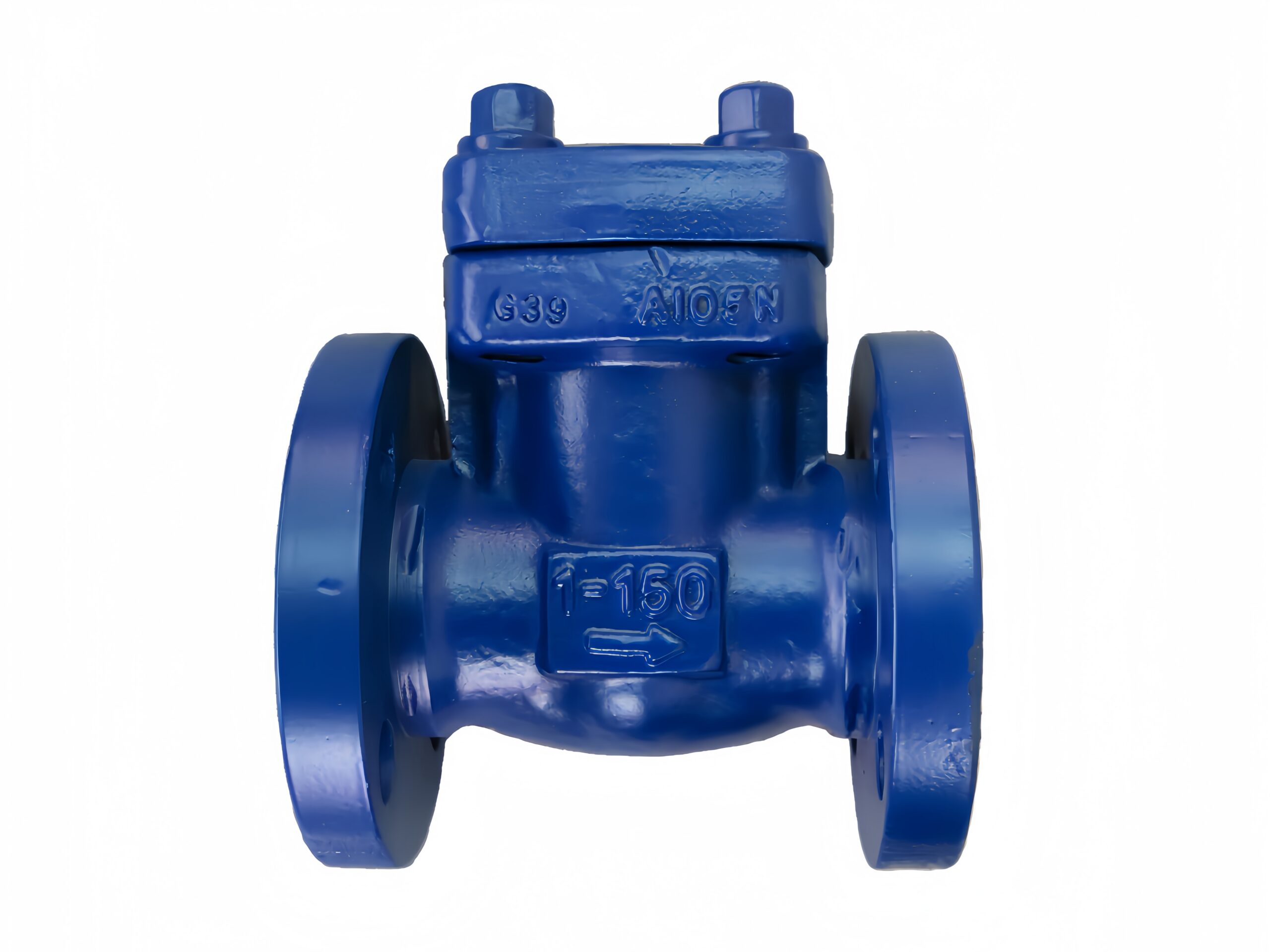
Lifting Check Valve Closed Die Forged—1″ 150LB RF
Description
Technical Data Sheet
Lifting Check Valve, Closed Die Forged
Size & Class: 1″ 150LB RF
Body Material: ASTM A105N
1. General Description
This is a closed die forged, lifting type check valve. Both the body and bonnet are integrally forged using the closed die process from ASTM A105N normalized carbon steel, providing excellent structural density and mechanical properties. The valve operates by medium pressure lifting the disc along a guide sleeve, allowing flow in one direction only and automatically closing to prevent reverse flow. Standard installation is on horizontal piping (with the disc moving vertically); vertical flow configurations are available on request. Flanged ends comply with ASME B16.5 Raised Face (RF) standard, Class 150.
2. Design Codes & Standards
Item Applicable Standard
Design & Manufacture API 602, BS 5352, ASME B16.34
Pressure-Temperature Rating ASME B16.34
End Connections ASME B16.5 (RF)
Face-to-Face Dimensions ASME B16.10
Inspection & Testing API 598, API 602
Forging Standard ASTM A105 / A105N
3. Main Technical Specifications
Nominal Size: 1″ (DN25)
Pressure Class: Class 150 (150LB)
Connection Type: Flanged RF
Body/Bonnet Material: ASTM A105N (Closed Die Forged)
Disc Material: A105 + Stellite 6 overlay (Standard) / SS316+Stellite (Optional)
Body Seat Face: Integral Stellite 6 overlay
Guide Sleeve Material: 13Cr or SS304
Gasket: 304+Graphite Spiral Wound / 316+Graphite
Service Media: Water, steam, oil, natural gas, etc.
Temperature Range: -29 °C to +425 °C (-20 °F to +800 °F)
Installation Orientation: Horizontal pipeline (disc lifts vertically); flow direction arrow must be observed.
4. Materials of Major Parts
No. Part Name Material Standard
1 Body A105N ASTM A105
2 Bonnet A105N ASTM A105
3 Disc A105 + STL.6 Overlay ASTM A105
4 Seat Integral STL.6 Overlay —
5 Guide Sleeve 13Cr / SS304 —
6 Bonnet Gasket 304+Graphite Spiral Wound —
7 Stud A193 B7 ASTM A193
8 Nut A194 2H ASTM A194
5. Principal Dimensions (1″ 150LB RF)
Symbol Description Value (mm) Value (inch)
L Face-to-Face Length 127 5.00″
D Flange Outer Diameter 108 4.25″
D1 Bolt Circle Diameter 79.4 3.12″
D2 Bolt Hole Diameter 15.9 0.63″
b Flange Min. Thickness (incl. RF) 11.2 0.44″
H Centerline to Top of Bonnet (approx.) 75 2.95″
Weight Approx. Weight ~3.5 kg —
Bolt Holes — 4 —
Note: Dimensions conform to ASME B16.10 and B16.5. Final confirmed dimensions are subject to the approved drawing.
6. Performance Tests & Inspection
Shell Strength Test: 1.5 × Class 150 rated pressure (approx. 28.5 bar), hold time ≥1 minute, no visible leakage or structural damage.
Seat Tightness Test (High/Low Pressure): 1.1 × rated pressure (approx. 21 bar) water / 0.6 bar pneumatic, zero leakage.
Disc Operation Check: Disc lifts freely without sticking and reseats properly.
Visual & Dimensional Inspection: 100% visual inspection free from forging defects such as cracks or laps; face-to-face and flange dimensions fully checked.
Material Certification: EN 10204 Type 3.1 material certificate available upon request; PMI spectral analysis available as an option.
7. Installation & Maintenance Tips
Ensure the flow direction of the medium matches the arrow cast on the valve body. Reverse installation will prevent the valve from closing.
Standard lifting check valves are designed for horizontal pipelines with the disc axis vertical. For vertical flow applications, specify a model with a spring-assisted closure mechanism.
When welding or making flange connections, keep the valve in the closed position to protect the seating surfaces from weld spatter damage.
For high-temperature service, re-tighten the bonnet bolts after the valve reaches operating temperature to compensate for thermal expansion.
Periodically check that the valve operates without sticking. If necessary, disassemble and clean the sealing surfaces and guide sleeve.
This technical data sheet is for selection reference only. The manufacturer reserves the right to change the design without prior notice. Final order shall be based on the approved drawing.