B148 C95800 AL-Bronze Dual Plate Check Valves
Description
ASTM B148 C95800 Aluminum Bronze Dual Plate Check Valve
Technical Data Sheet
1. Product Overview and Applications
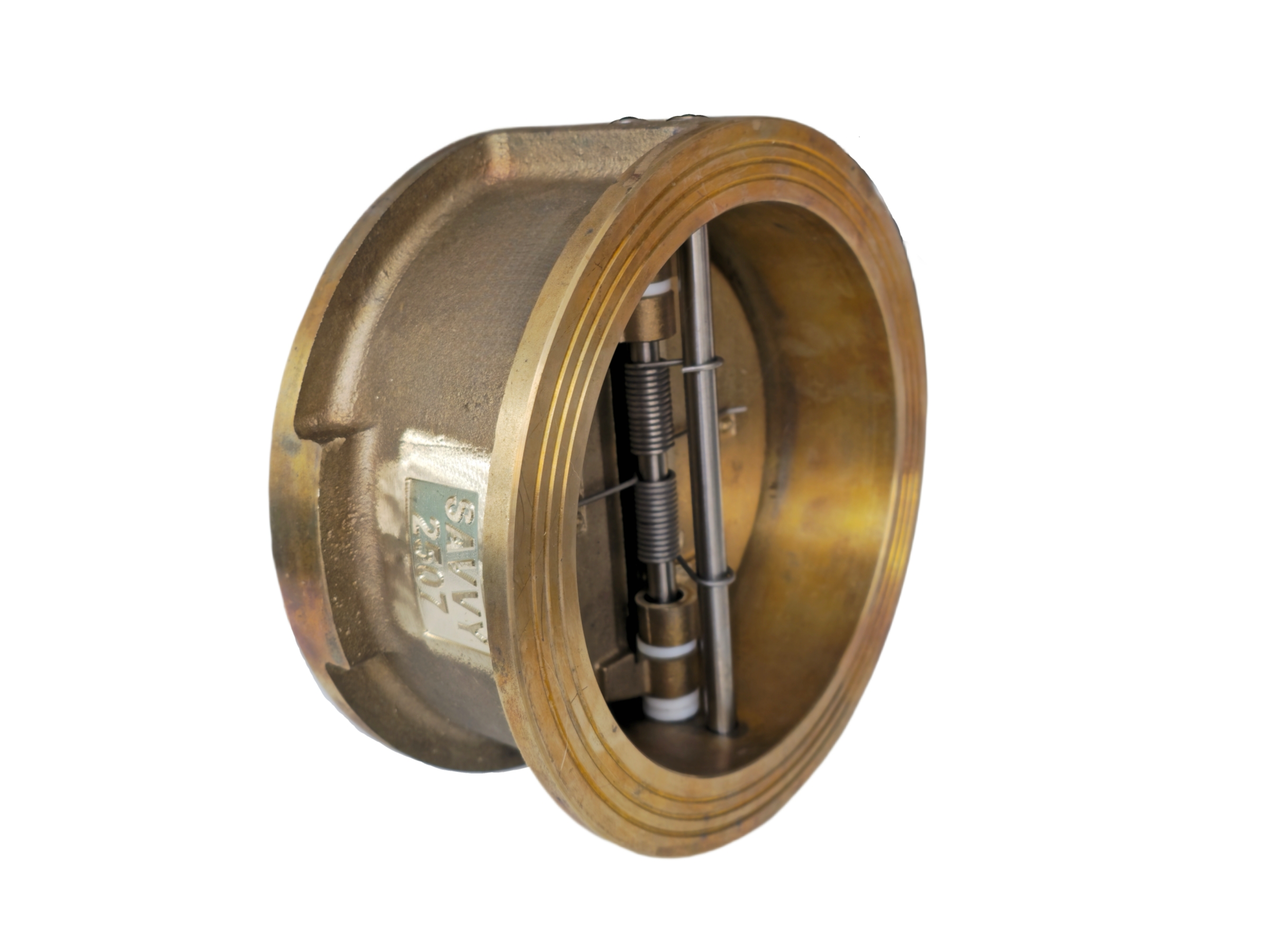
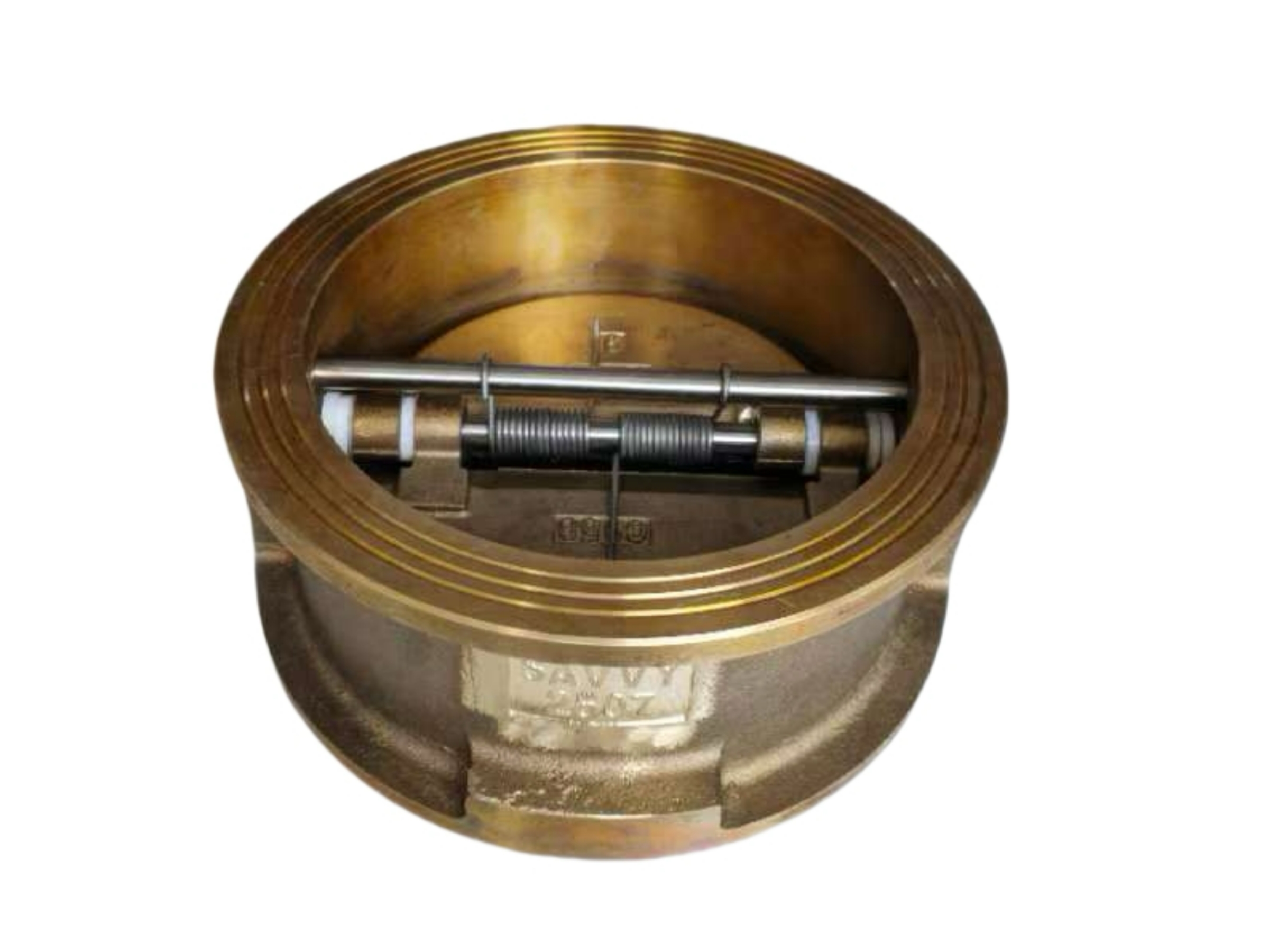
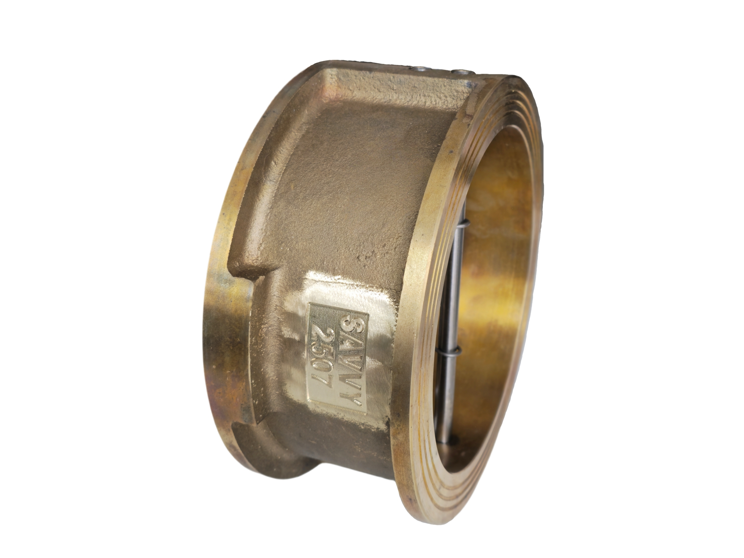
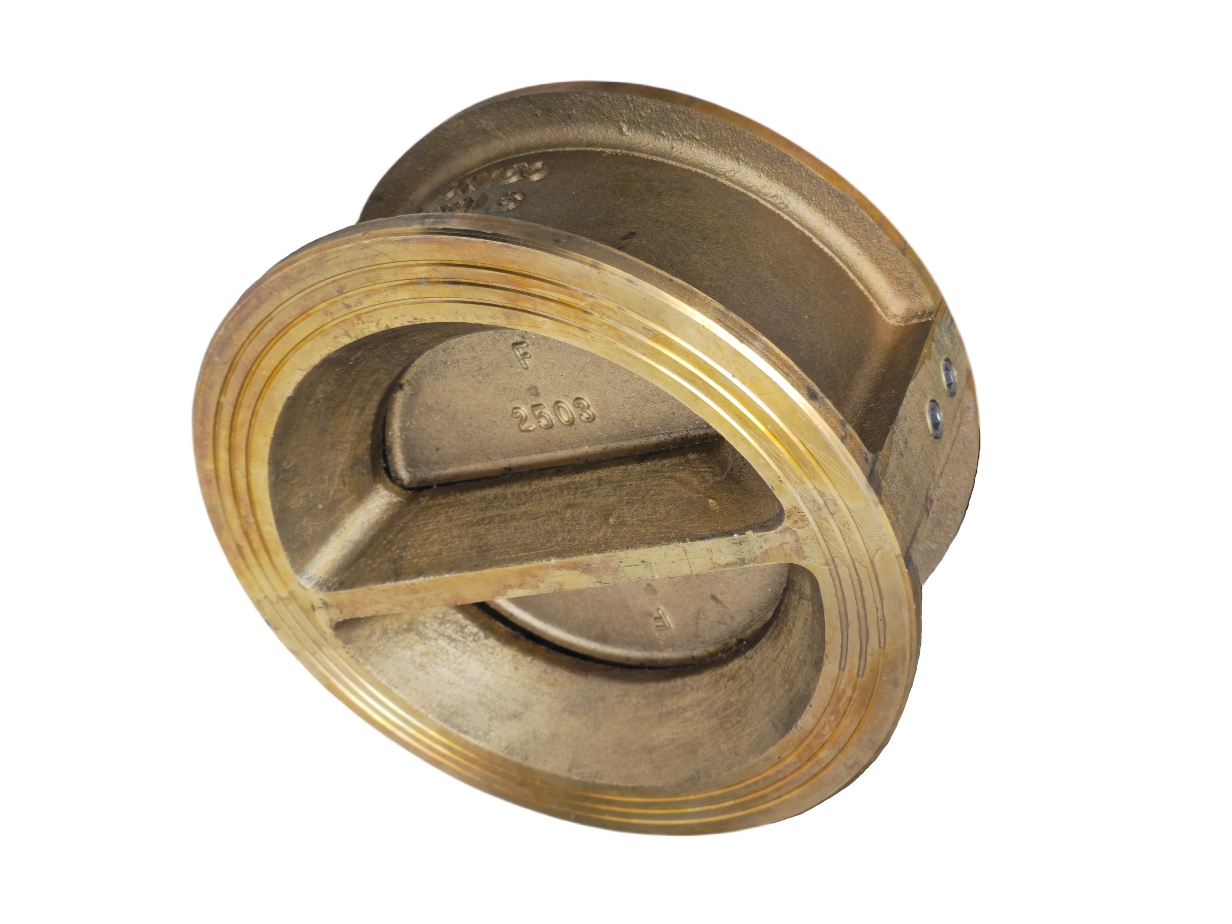
ASTM B148 C95800 aluminum bronze dual plate check valves are designed for reliable, unidirectional flow control and backflow prevention in highly corrosive and erosive environments. The dual plate, wafer-type design features two spring-loaded, semi-circular discs that pivot on a central hinge pin. This configuration offers a compact, lightweight, and robust solution with lower cracking pressure and faster dynamic response compared to conventional swing check valves.
The C95800 nickel-aluminum bronze alloy provides exceptional resistance to seawater corrosion, cavitation damage, and erosion-corrosion, making these valves the ideal choice for critical marine and offshore services.
Typical Industries: Marine engineering, shipbuilding, offshore oil & gas platforms, seawater desalination plants, coastal power generation, chemical processing, and fire protection systems.
Common Systems: Seawater cooling lines, ballast water systems, firewater ring mains, brine recirculation, and pumped discharge lines where swift, non-slam closure is essential.
Suitable Media: Seawater, brackish water, brine, non-oxidizing acids, alkaline solutions, and other compatible fluids.
Key Advantages: Compact wafer body fits between standard flanges, reducing weight and installation space. The spring-assisted closure ensures rapid seating and effectively minimizes water hammer and surge pressures during flow reversal.
2. Technical Specifications and Design Standards
These check valves are engineered to meet stringent international standards, ensuring interoperability, reliability, and long service life.
Design & Manufacturing Standards: API 594 (Face-to-Face Dimensions), API 6D (if specified), ASME B16.34, MSS SP-67
Valve Type: Dual plate, wafer check valve with spring-loaded closure. Retractable or non-retractable pin design, with or without external actuation options.
Face-to-Face Dimension: API 594 (Short Pattern) or ASME B16.10 / ISO 5752 as applicable.
Flange Compatibility: Designed to mount between ASME B16.5 (Class 150 – 2500) or EN 1092-1 flanges. Wafer body fits both flat face and raised face flanges.
Nominal Size (DN) : 2 inches through 84 inches (DN50 – DN2100) and larger, subject to manufacturer’s range.
Pressure Class: Class 150 LB through Class 2500 LB (PN10 – PN420)
Temperature Range: Typically -29°C to +200°C (-20°F to +392°F); extended temperature ranges up to 400°C (752°F) may be available with specific trim and gasket materials. Always consult the manufacturer for your service conditions.
Valve Marking: In accordance with MSS SP-25, including material designation, heat number, size, class, and manufacturer identification.
3. Core Material: ASTM B148 C95800 (UNS C95800)
C95800 is a nickel-aluminum bronze alloy that delivers an outstanding combination of high strength, hardness, and corrosion resistance in seawater and aggressive chemical environments. Its anti-galling properties and resistance to biofouling further enhance valve reliability.
3.1 Chemical Composition (Weight %)
Element Content (%) Remarks
Copper (Cu) ≥79.0 Remainder
Aluminum (Al) 8.5 – 9.5 Provides exceptional corrosion resistance by forming a tenacious oxide layer
Nickel (Ni) 4.0 – 5.0 Enhances strength, toughness, and resistance to erosion-corrosion; includes Cobalt
Iron (Fe) 3.5 – 4.5 Grain refiner; increases tensile strength and wear resistance
Manganese (Mn) 0.8 – 1.5 Acts as a deoxidizer and improves castability
Lead (Pb) ≤ 0.03 (Impurity) Restricted to prevent hot cracking during manufacturing
Silicon (Si) ≤ 0.10 (Impurity) Controlled to maintain ductility
3.2 Mechanical & Physical Properties (Typical Values)
Property Typical Value
Tensile Strength ≥ 585 MPa (85 ksi)
Yield Strength (0.2% offset) ≥ 240 MPa (35 ksi)
Elongation ≥ 15% (in 2-inch gauge length)
Brinell Hardness (BHN) 159 – 190 HB
Density 7.64 g/cm³
Modulus of Elasticity 117 GPa
Thermal Conductivity 36.0 W/m·K @ 20°C
4. Principal Component Materials
Material selection for each component is critical for ensuring tight shut-off, wear resistance, and corrosion compatibility.
Component Material Grade Standard / Remarks
Body ASTM B148 C95800 Wafer-type body, full nickel-aluminum bronze construction
Discs (Plates) ASTM B148 C95800 Matched with body for uniform corrosion and thermal expansion characteristics
Seat Ring / Sealing Face ASTM B148 C95800 (Integral) or PTFE / RPTFE (Soft-Seated) Metal-to-metal seating as standard; soft inserts available for zero-leakage service at moderate temperatures
Hinge Pin ASTM B150 C63000 or Super Duplex Stainless Steel (e.g., UNS S32750) High strength, excellent corrosion fatigue resistance
Torsion Spring(s) Hastelloy C-276 (UNS N10276), Inconel X-750, or Super Duplex SS Spring material selected for specific media compatibility and service temperature
Stop Pin / Retaining Plate ASTM B150 C63000 or equivalent Secures hinge pin and prevents disc over-travel
Gasket (if body halves exist) PTFE / Spiral Wound Graphite-filled For designs with bolted body halves; ensures body joint leak tightness
Hinge Pin Bushings RPTFE / Graphite-filled Bronze Minimizes friction and wear at the pivot point; ensures smooth disc movement
5. Testing and Inspection Specifications
Each valve is subjected to rigorous testing prior to delivery to verify structural integrity and seat tightness.
Test Item Applicable Standard Test Requirement
Shell Strength Test API 598 / BS EN 12266-1 Test pressure of 1.5 times the rated working pressure; no visible leakage or permanent deformation is permitted
Seat Leak Tightness Test API 598 / BS EN 12266-1 Test pressure of 1.1 times the rated working pressure; leakage rate must comply with the specified leakage class (standard or zero leakage)
Disc Operability Test Manufacturer’s Specification Verify discs open smoothly with minimal differential pressure and close promptly without binding
Optional Tests Cryogenic testing, fire-safe test (API 607 / API 6FA), fugitive emissions test, helium mass spectrometer leak test Available upon customer request for critical applications
6. Installation, Operation, and Maintenance Guide
To ensure optimal valve performance and service life, observe the following instructions:
Installation Orientation: Dual plate check valves may be installed in both horizontal and vertical (upward flow only) pipelines. The preferred orientation is with the hinge pin horizontal. When installed in vertical lines, ensure the flow direction arrow on the body points upward and is strictly aligned with the media flow.
Minimum Backpressure Required: The valve must see sufficient backpressure to maintain the discs fully open during steady flow. Continuous operation at very low flow velocity may cause disc fluttering, leading to premature wear of the hinges and seats. Select spring assistance suitable for the expected flow regime.
Pipeline Considerations: Ensure no foreign matter (weld spatter, debris, etc.) is present in the pipeline before installation. A strainer upstream is recommended where debris could impede disc closure.
Fastener Integrity: For valves with bolted body halves, periodically check bolt torque according to the manufacturer’s maintenance manual to ensure body joint integrity, especially after thermal cycling.
Routine Inspection: During planned shutdowns, visually inspect the discs, seat faces, and springs for signs of wear, corrosion, or fouling. Clean marine growth or scale deposits from sealing faces. Replace any worn springs or bushings to maintain reliable non-slam operation.
Storage: Valves not in immediate service should be stored in a clean, dry environment with the discs in the fully closed position and protective end covers fitted.