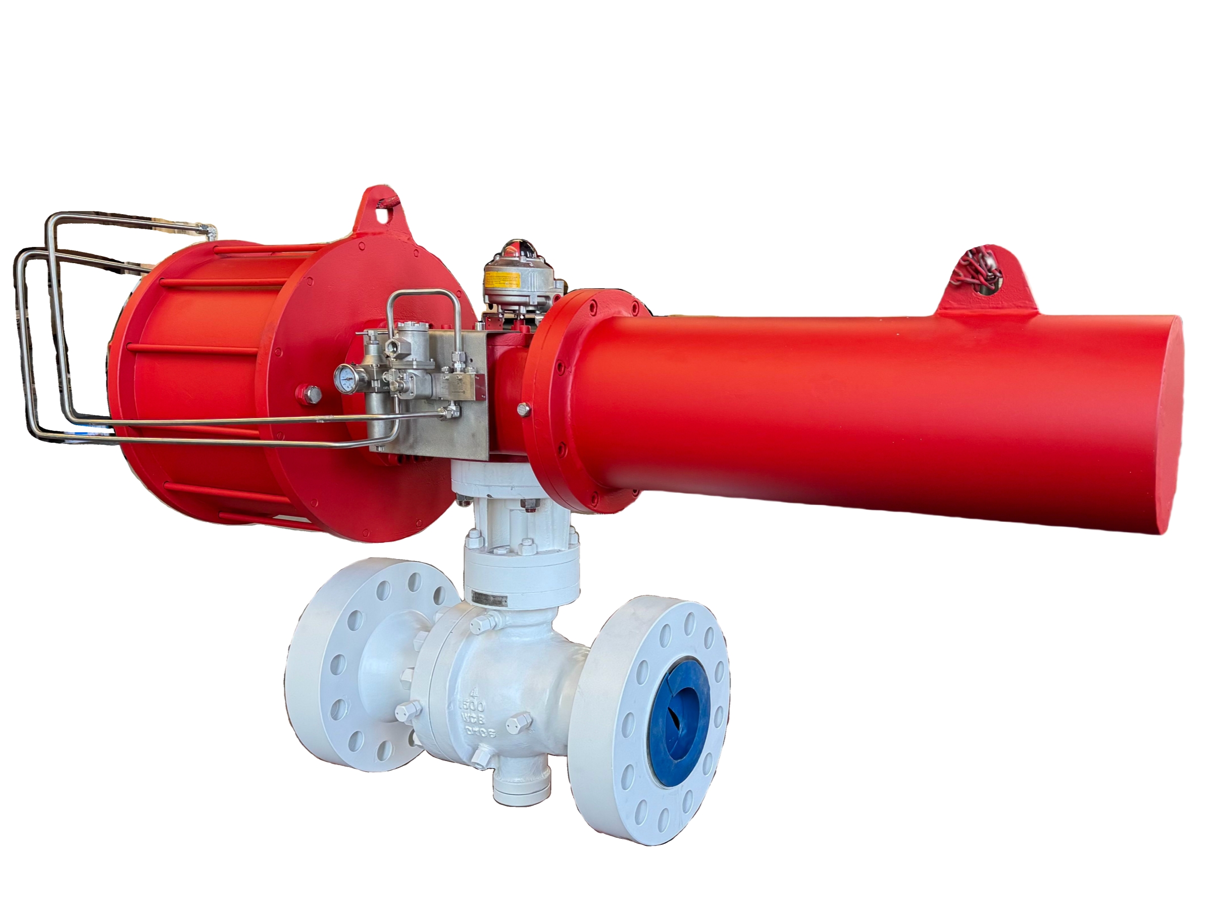
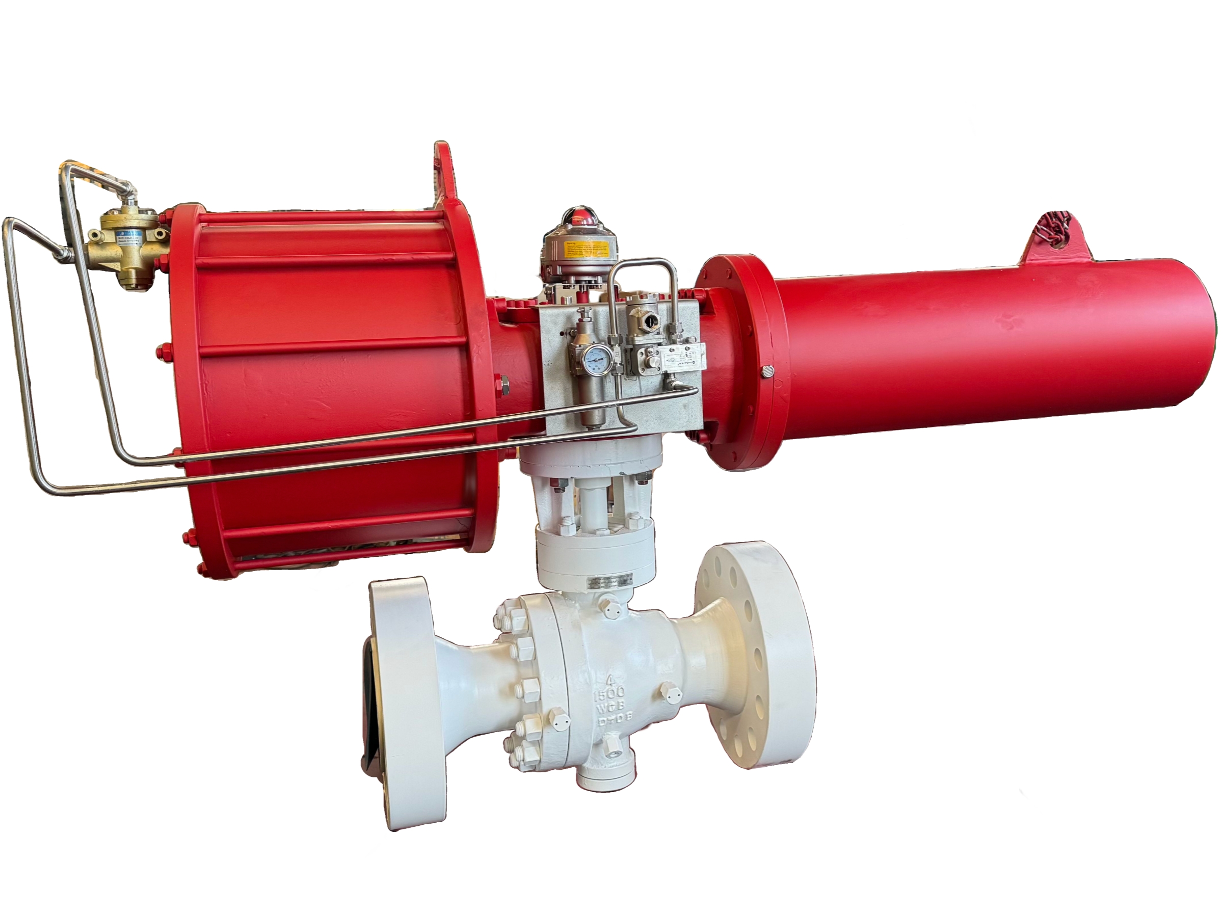
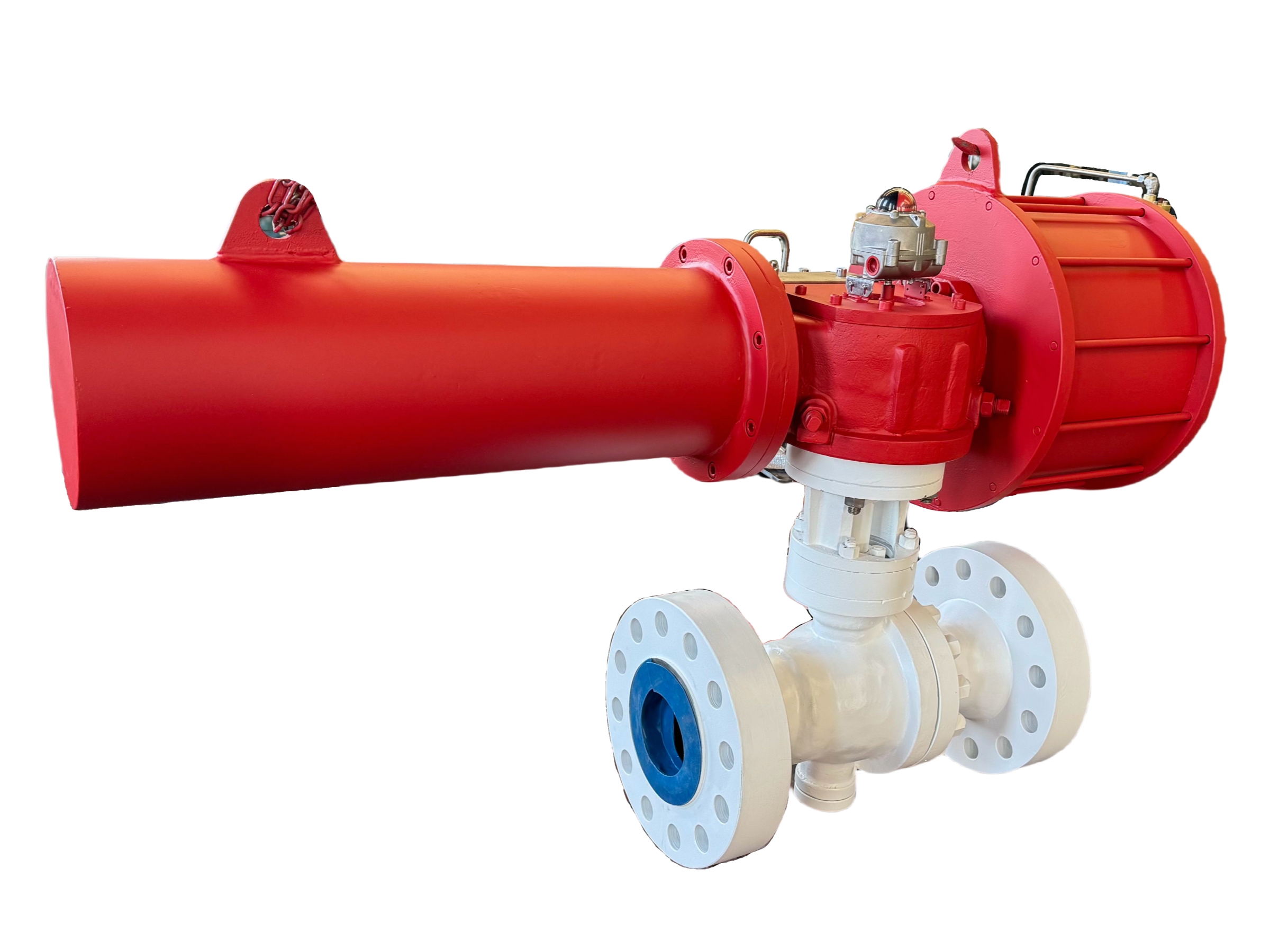
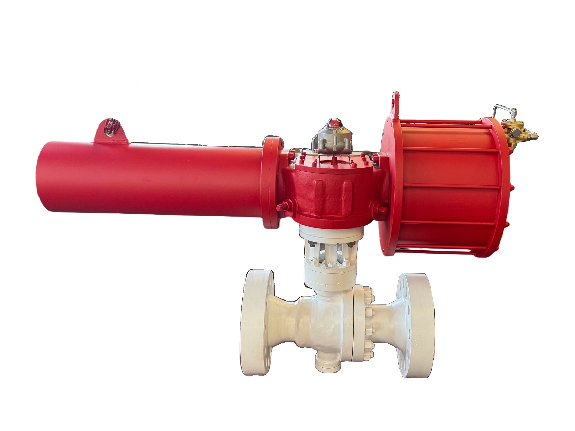
Emergency Shut-down Trunnion Ball Valves— 6″ x 4″ 1500LB RTJ
Description
Technical Data Sheet
Emergency Shut-Down (ESD) Trunnion Ball Valve
Size: 6″ x 4″ (DN150 x DN100) Reduced Bore
Pressure Class: 1500LB
End Connection: Ring Type Joint (RTJ) Flanged
1. General Description
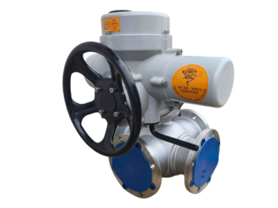
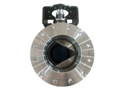
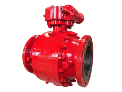
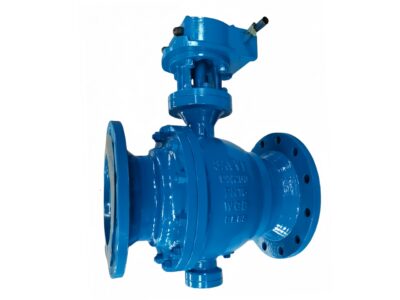
This trunnion-mounted ball valve is specifically configured for Emergency Shut-Down (ESD) service in high-pressure oil and gas, refining, petrochemical, and transmission systems. The 6″ x 4″ reduced bore design optimizes downstream piping and actuator sizing while meeting flow requirements. The valve features a two-piece, side-entry, cast body, with spring-energized seats and a blow-out proof stem. It is designed to couple with a fail-safe pneumatic, hydraulic, or electric actuator to achieve reliable, rapid closure upon loss of power or signal, meeting SIL 2/SIL 3 safety integrity levels when properly engineered. Fire-safe, anti-static, and double piston effect (DPE) seat options ensure tight shutoff in both directions and safety during emergency events.
2. Design Codes & Standards
Item Applicable Standard
Design & Manufacture API 6D, ASME B16.34, API 608
Pressure-Temperature Rating ASME B16.34
Flanged Ends (RTJ) ASME B16.5
Face-to-Face Dimensions ASME B16.10 (Long Pattern)
Inspection & Testing API 6D, API 598
Fire-Safe Design API 607 / ISO 10497
Fugitive Emissions ISO 15848-1 (optional)
Safety Integrity Level (SIL) IEC 61508 certified actuator & valve assembly (on request)
Casting Standard ASTM A216, A352, A351 etc.
3. Main Technical Specifications
Nominal Size: 6″ inlet × 4″ outlet (DN150 × DN100)
Pressure Class: Class 1500 (1500LB)
End Connection: RTJ flanges per ASME B16.5
Bore Type: Reduced Bore (full bore option available as 6″×6″)
Body Material (Cast): ASTM A216 WCB (standard); WCC, LCC, CF8M, Duplex available on request
Ball Material: A105 with Electroless Nickel Plating (ENP) / SS316 with chrome carbide coating
Seat Design: Double Piston Effect (DPE) for bidirectional tight shutoff; Self-relieving (SPE) available for cavity pressure relief
Seat Material: Devlon, PEEK, or Nylon for high-pressure and abrasive service
Stem Material: 17-4PH / A638 660 (Inconel overlay on seating optional)
Packing: Graphite for fire-safe, fugitive emission control
Bolting: A193 B7 / A194 2H (standard); A193 B16 / A194 7 for high-temperature
Design Features:
Trunnion mounted ball with integral bearing supports
Blow-out proof stem
Antistatic device (electrical continuity)
Fire-safe certified (API 607/ISO 10497)
Emergency sealant injection connections (on body and stem)
Cavity vent/drain ports for double block & bleed verification
Gear operator or direct actuator coupling with ISO 5211 top flange and stem adaptor
4. Materials of Major Parts (Typical WCB / 17-4PH Stem)
No. Part Name Material (Standard) Standard
1 Body ASTM A216 WCB ASTM A216
2 Bonnet ASTM A216 WCB ASTM A216
3 Ball A105 + ENP ASTM A105
4 Seat Ring Devlon / PEEK —
5 Stem ASTM A564 17-4PH ASTM A564
6 Bearings (Stem/Ball) SS316 + PTFE —
7 Packing Graphite —
8 Body Gasket Spiral Wound 316L+Graphite ASME B16.20
9 Stud A193 B7 ASTM A193
10 Nut A194 2H ASTM A194
11 Gear Operator / Actuator Bracket Ductile Iron / Carbon Steel ISO 5211
5. Principal Dimensions (6″ × 4″ 1500LB RTJ)
Symbol Description Value (mm) Value (inch)
L Face-to-Face Length 737 29.02″
D (6″) Flange OD (6″ RTJ) 394 15.50″
D (4″) Flange OD (4″ RTJ) 292 11.50″
b (6″) Flange Thickness (6″ 1500#) 68.3 2.69″
b (4″) Flange Thickness (4″ 1500#) 54.0 2.13″
H Center to Top of Gear/Actuator Pad (approx.) ~550 (gear) ~21.7″
ISO Pad Actuator Mounting Flange F14 / F16 —
Cv Rated Flow Coefficient (Reduced Bore) ~450 —
Weight Approx. Weight (valve only) ~850 kg —
Bolt Holes (6″) 8 × 1.625″ — —
Bolt Holes (4″) 8 × 1.25″ — —
*Note: Face-to-face for 6″×4″ Class 1500 reduced bore is often per manufacturer’s standard; the dimension shown is typical. Final dimensions to be confirmed on the approved drawing. RTJ groove numbers: R47 (6″) and R39 (4″).*
6. Performance Tests & Inspection
Shell Test: 1.5 × Class 1500 rated pressure (approx. 77.6 MPa / 11200 psig), water, hold time per API 6D, no leakage or deformation.
Seat Test (High Pressure): 1.1 × rated pressure (approx. 56.9 MPa / 8260 psig), water, zero leakage.
Low-Pressure Seat Test: 0.6 bar pneumatic, zero leakage.
Fire-Safe Test: Per API 607 / ISO 10497; valve must maintain seat tightness during and after fire.
Cryogenic or Low-Temp (if specified): Per BS 6364 for LCC/SS bodies.
Actuator Integration: Full stroke test at minimum, maximum, and fail-safe spring settings (if pneumatic). Verify closure time meets ESD requirements (e.g., < 2 seconds per inch of diameter).
Material Certification: EN 10204 Type 3.1 for all pressure-containing parts; PMI optional.
7. ESD Actuator Configuration (Typical)
The valve is normally supplied without the actuator, but prepared with a standard ISO 5211 pad and stem adaptor. For a complete ESD valve package, the following typical actuator data is required:
Actuator type: Pneumatic (scotch-yoke or rack & pinion), hydraulic, or electro-hydraulic
Fail-safe mode: Spring return (fail-close or fail-open) per ESD philosophy
Supply pressure: e.g., 6-10 bar instrument air
Closing time: < 2 seconds (full stroke)
Solenoid valve: 24 VDC, ATEX certified
Limit switches: 2 proximity switches for open/close indication
Partial Stroke Testing (PST): Capable if required
SIL certification: IEC 61508 SIL 2/3 loop-compatible
8. Installation & Maintenance Tips
RTJ Flanges: Use ring gaskets of the correct material and hardness (typically soft iron or SS316). Ensure flange faces and ring grooves are clean and undamaged.
Valve Support: Due to the high weight (approx. 850 kg), install independent pipe supports or a valve support saddle. Do not let the valve weight hang on the RTJ connections.
Cavity Vent/Drain: During hydrotesting and commissioning, operate the cavity vent/drain per double block & bleed procedures. The cavity must be depressurized before any maintenance.
Seat Type: DPE seats will trap pressure in the cavity – an external thermal relief valve is strongly recommended if the valve is expected to see temperature variations while closed.
ESD Testing: Periodically test the actuator closure time and partial stroke. Re-inject emergency sealant after testing to maintain seat integrity.
Sealant Injection: Use only approved sealants compatible with the service. Inject at the recommended pressure to avoid damaging the seats.
This technical data sheet is for selection and engineering reference. The manufacturer reserves the right to modify designs without prior notice. All final specifications are to be agreed upon in the project-specific data sheets and approved drawings.