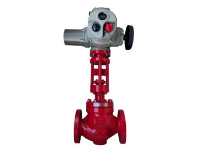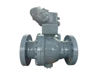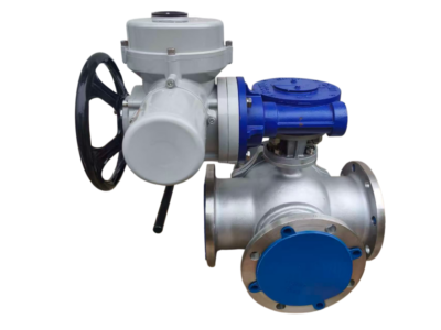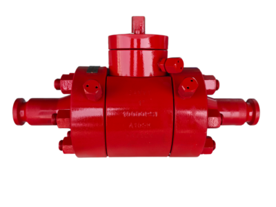
V-port Control Ball Valve Trunnion Mounted Ready for Actuators
Description
TECHNICAL DATA SHEET
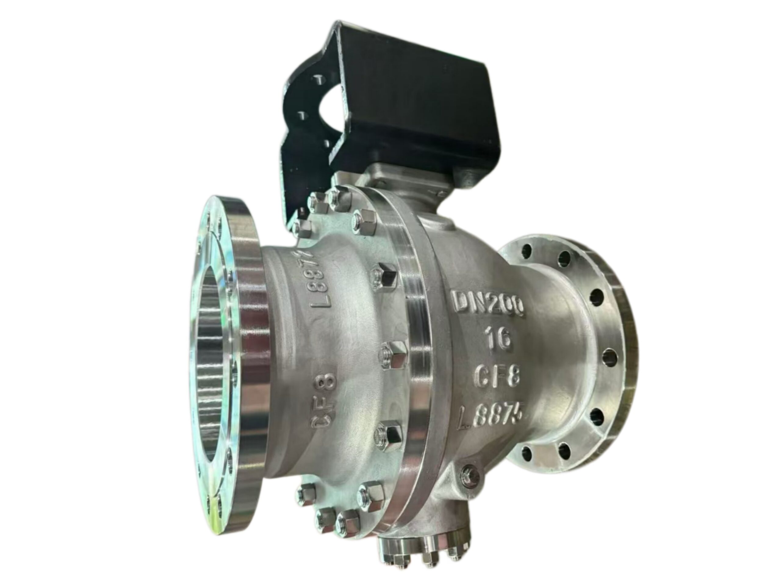
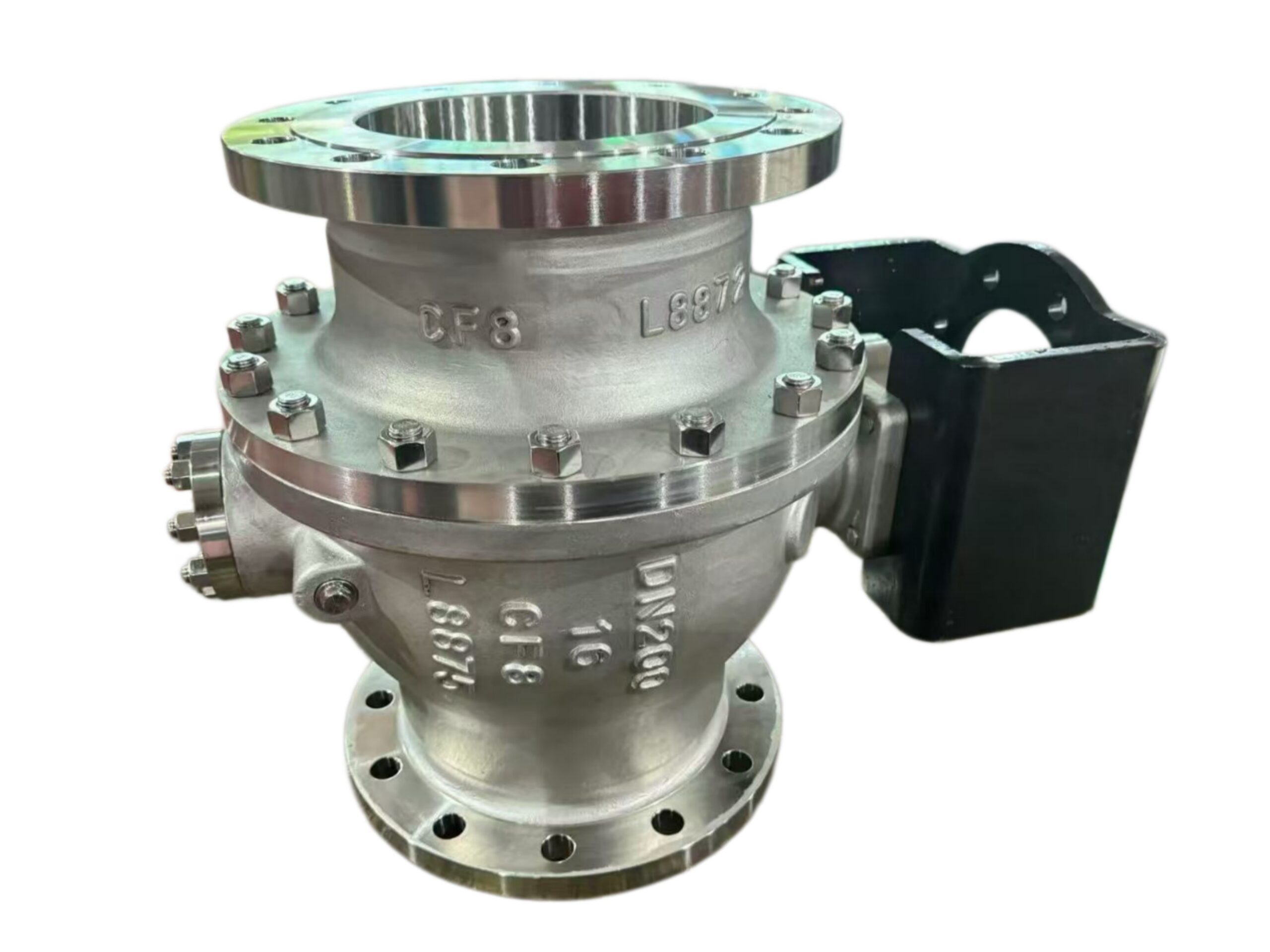
V-PORT CONTROL BALL VALVE – TRUNNION MOUNTED
Segmented V‑Notch Ball · Flanged / Wafer / BW
Typical Size Range: DN25 – DN600 (1″ – 24″)
Pressure Class: ASME 150 / 300 / 600 (PN16 – PN100)
Flow Characteristic: Modified Equal Percentage
End Connections: RF Flanged, Wafer, Butt‑Weld
1. GENERAL DESCRIPTION
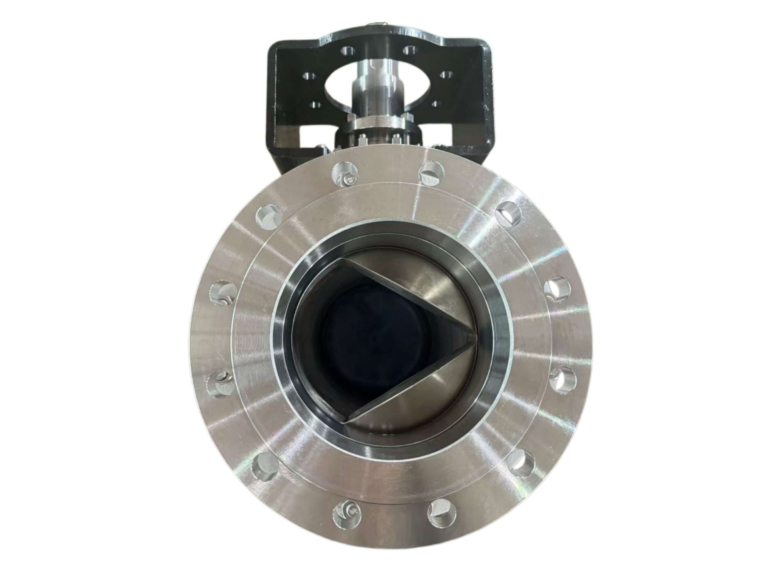
The V‑port control ball valve features a trunnion‑mounted, segmented ball with a precision‑machined V‑shaped notch. The trunnion design absorbs high thrust loads, reduces operating torque, and ensures stable positioning even at high differential pressures. The V‑notch profile provides an inherent modified equal percentage flow characteristic, delivering excellent rangeability and fine throttling control particularly at low openings. The shearing action between the ball’s V‑edge and the seat ring makes the valve suitable for media containing solids, fibers, or viscous fluids (pulp & paper stock, slurry, waste water, etc.). The design is fully bi‑directional and can be supplied with soft, metal, or combination seats to meet a range of shut‑off requirements.
2. APPLICABLE STANDARDS
| Parameter | Standard |
|---|---|
| Basic Valve Design | API 6D / ISO 17292, API 608 (ball valves) – trunnion mounted |
| Face‑to‑Face (Flanged) | ASME B16.10 Long/Short pattern or Manufacturer’s Standard |
| Face‑to‑Face (Wafer) | Manufacturer’s Standard (typically compact) |
| Flange Dimensions | ASME B16.5 (up to 24″) / EN 1092‑1 |
| Butt‑Weld Ends | ASME B16.25 |
| Pressure‑Temperature Ratings | ASME B16.34 |
| Seat Leakage Classification | ANSI/FCI 70‑2 (Class IV, V or VI) |
| Testing | API 598 / ISO 5208 + ANSI/FCI 70‑2 seat leakage |
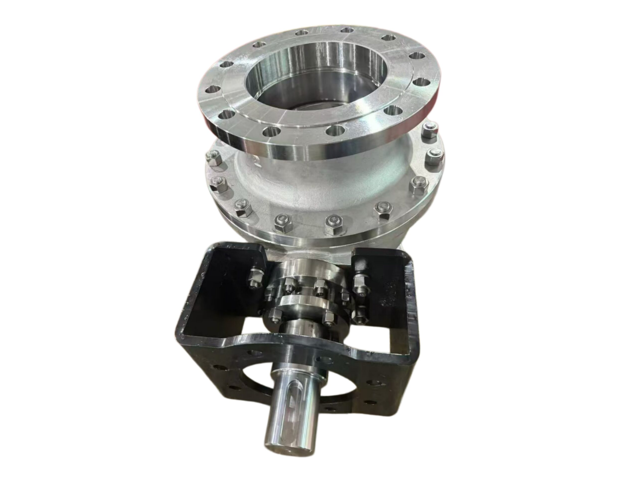
| Actuator Mounting | ISO 5211 mounting flange on yoke/bracket |
3. TECHNICAL SPECIFICATIONS
| Parameter | Value / Description |
|---|---|
| Valve Type | Trunnion mounted, segmented V‑port ball, full‑bore or reduced‑bore |
| Nominal Size Range | DN25 to DN600 (1″ to 24″) – larger sizes on request |
| Pressure Class | ASME 150, 300, 600 (PN16, 40, 100) |
| Flow Characteristic | Modified equal percentage (standard V‑notch 30° or 45°). Other V‑angles on request |
| Rangeability | 100:1 to 300:1 depending on V‑notch angle |
| Seat Leakage (Soft Seat) | ANSI/FCI 70‑2 Class VI – bubble‑tight |
| Seat Leakage (Metal Seat) | ANSI/FCI 70‑2 Class IV (Class V optional with special lapping or alloy) |
| Flow Direction | Bi‑directional. Preferred: flow into the V‑side of the ball (self‑cleaning shear) |
| Body Style | Two‑piece or three‑piece forged or cast body (flanged, wafer, or butt‑weld ends) |
| Body Material | ASTM A216 WCB/WCC (carbon steel), ASTM A351 CF8M (316 SS), Duplex, Super Duplex etc. |
| Ball / V‑Segment Material | ASTM A351 CF8M / A479 316, hard chrome plated or Stellite®‑overlay V‑edge |
| Seat Ring | PTFE (Teflon®), RTFE (15% GF), PEEK, or metal seated (Stellite® overlay) |
| Stem Material | ASTM A276 316 SS, 17‑4PH, or Duplex, anti‑blowout design |
| Trunnion / Bearings | PTFE‑lined, metal‑backed bearings; lower trunnion 316 SS hardfaced |
| Packing | PTFE V‑ring / Graphite, live‑loaded (ISO 15848‑1 fugitive emission optional) |
| Bolting | ASTM A193 B7 / B8M, zinc plated or PTFE coated |
| Operation | Bare stem for actuator mounting (ISO 5211). Manual gear operator for isolation duty (option) |
4. MATERIALS OF CONSTRUCTION (Typical – Flanged Carbon Steel Body)
| Part No. | Component | Material Standard & Grade |
|---|---|---|
| 1 | Body (2‑piece) | ASTM A216 WCB (carbon steel) |
| 2 | Ball / V‑Segment | ASTM A351 CF8M (316 SS), hard chrome plated / Stellite® edge |
| 3 | Seat Ring | RTFE (Reinforced PTFE) with elastomer back‑up ring |
| 4 | Stem | ASTM A276 S31600 (316 SS), ground & polished |
| 5 | Trunnion (Lower) | ASTM A276 316 SS, Stellite® hardfaced tip |
| 6 | Bearings | PTFE fabric reinforced, metallic backing |
| 7 | Stem Packing | PTFE V‑ring set, Belleville washer live‑loading |
| 8 | Body Gasket | Spiral wound SS316 + Graphite / PTFE |
| 9 | Bolting (Body/Bonnet) | ASTM A193 B7 / A194 2H, coated |
| 10 | Yoke / Mounting Bracket | Carbon steel, painted / Stainless Steel |
For corrosive services, all wetted parts can be supplied in 316 SS, duplex or super duplex. For abrasive/high‑temp services, full Stellite®‑faced ball and seat are available.
5. FLOW CHARACTERISTICS & TYPICAL Cv VALUES
The V‑notch profile provides an inherent equal percentage characteristic. The table below gives approximate max Cv for a full‑bore, 30° V‑notch ball.
| Nominal Size DN / NPS | V‑notch Angle | Max Cv (approx.) – Class 150/300 RF |
|---|---|---|
| 25 (1″) | 30° | 8 |
| 40 (1½″) | 30° | 22 |
| 50 (2″) | 30° | 45 |
| 80 (3″) | 30° | 100 |
| 100 (4″) | 30° | 195 |
| 150 (6″) | 30° | 420 |
| 200 (8″) | 30° | 750 |
| 250 (10″) | 30° | 1200 |
| 300 (12″) | 30° | 1800 |
Available V‑notch angles: 15°, 30°, 45°, 60°, 90°. Reduced trims for lower Cv are standard. For exact sizing, the manufacturer’s Cv curves must be used together with process data.
6. PRESSURE – TEMPERATURE RATING (RTFE Seat, WCB Body, ASME Class 300)
| Temperature (°C) | Max. Working Pressure (bar) |
|---|---|
| -29 to 38 | 51.1 |
| 65 | 49.8 |
| 100 | 46.1 |
| 150 | 42.2 |
| 200 | 38.5 |
Higher temperatures require metal seats (Stellite®) or PEEK seats. For exact P‑T limits based on body and seat material, refer to manufacturer’s rating tables. Flanged valves comply with ASME B16.34.
7. DIMENSIONS & WEIGHTS (Flanged RF, ASME 300, ISO 5211 Actuator Mounted)
| DN | NPS | Face‑to‑Face L (mm) | Height H (centre to stem top) (mm) | Approx. Weight (kg) |
|---|---|---|---|---|
| 25 | 1″ | 165 | 220 | 11 |
| 40 | 1½″ | 190 | 260 | 18 |
| 50 | 2″ | 216 | 290 | 28 |
| 80 | 3″ | 283 | 360 | 48 |
| 100 | 4″ | 305 | 430 | 70 |
| 150 | 6″ | 403 | 520 | 135 |
| 200 | 8″ | 502 | 650 | 230 |
| 300 | 12″ | 648 | 850 | 520 |
Wafer body dimensions are significantly shorter. With gear operator or actuator, overall height increases; refer to outline drawings for specific actuator selection.
8. TESTING & INSPECTION
| Test Type | Test Medium | Test Pressure / Procedure | Acceptance Criteria |
|---|---|---|---|
| Shell Strength | Water | 1.5 × Maximum Design Pressure (ASME B16.34) | No leakage or deformation |
| Seat Leakage (Soft Seat) | Water | 1.1 × MAWP, then low‑pressure air | ANSI/FCI 70‑2 Class VI (bubble‑tight) |
| Seat Leakage (Metal Seat) | Water | 1.1 × MAWP | ANSI/FCI 70‑2 Class IV (or V as specified) |
| Functional Test | – | Full stroke, 0–100 % input signal | Smooth operation, repeatable position |
| Coating & Painting | Visual | DFT measurement | Min. 250 µm epoxy, no defects |
| Additional (Optional) | – | PMI, Charpy impact, cryogenic, fugitive emission | Per applicable standard |
Every control valve assembly includes a factory calibration certificate. EN 10204 3.1 material certificates and special testing are available.
9. OPTIONS & ACCESSORIES
-
Seat Materials: PEEK for temperatures up to 250 °C, metal (Stellite®) for abrasive or high‑temperature service, Cavity‑filled seats for solids.
-
V‑Notch Angles: 15°, 30°, 45°, 60°, 90° to tailor inherent flow characteristic.
-
Noise & Cavitation Trim: Multi‑stage cage / drilled ball options for anti‑cavitation and low noise.
-
Actuation: Bare stem with ISO 5211 flange. Compatible with pneumatic, electric, hydraulic actuators and manual gear operators. Typical smart positioner with 4–20 mA + HART®.
-
Fail‑Safe Action: Spring‑return pneumatic actuator (air fail‑close / fail‑open) or electric with battery backup.
-
End Connections: Wafer‑style body for compact installation, butt‑weld ends, RTJ flanges.
-
Extended Bonnet: For cryogenic or high‑temperature services.
-
Locking Device: Lockable in fully open or closed position.
-
Certifications: SIL capability, ATEX, PED 2014/68/EU, NACE MR0175/ISO 15156, CRN, WRAS (for potable water).
10. ORDERING INFORMATION
To specify this V‑port control ball valve, please provide:
-
Valve type: Trunnion Mounted V‑Port Control Ball Valve
-
Nominal size and pressure class: DN____ / ASME Class____ / PN____
-
Body & trim material: Carbon Steel / SS316 / etc.
-
Seat material & required leakage class: RTFE Class VI / Stellite Class IV / etc.
-
V‑notch angle & required Cv (or process data for sizing)
-
End connection: Flanged / Wafer / BW
-
Actuator type & signal: Manual / Pneumatic (fail action, supply pressure) / Electric (voltage, 4–20 mA)
-
Service medium, temperature, and inlet/outlet pressure
-
Special requirements: fugitive emission, NACE, ATEX, etc.
This data sheet describes a standard trunnion‑mounted V‑port control ball valve. Final material selection, trim design and actuator sizing must be performed by the manufacturer to ensure optimum control performance and mechanical integrity under the specified service conditions.