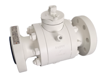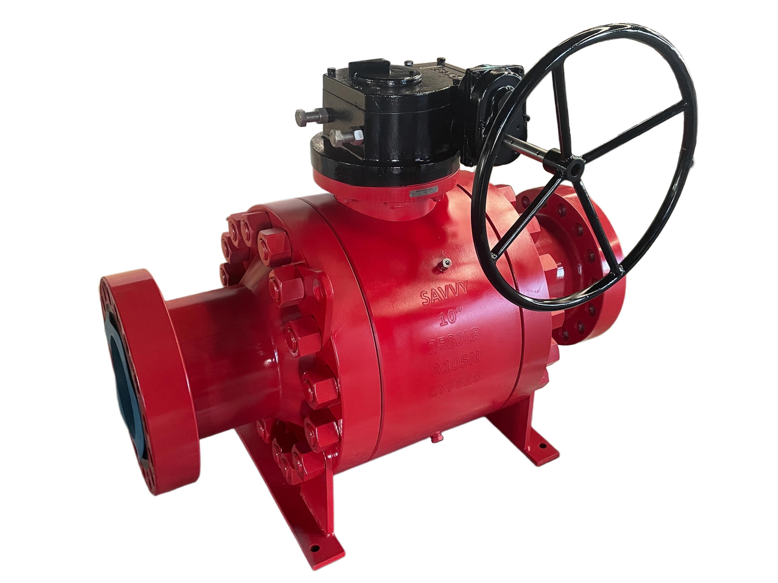
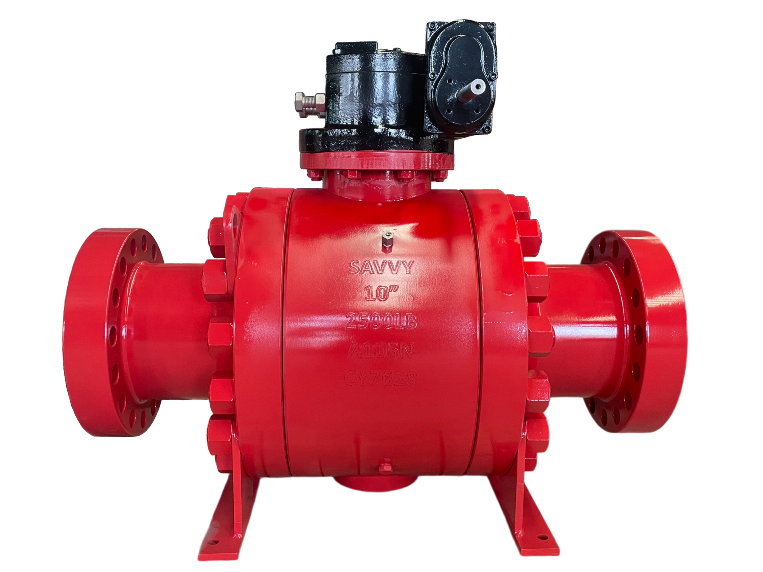

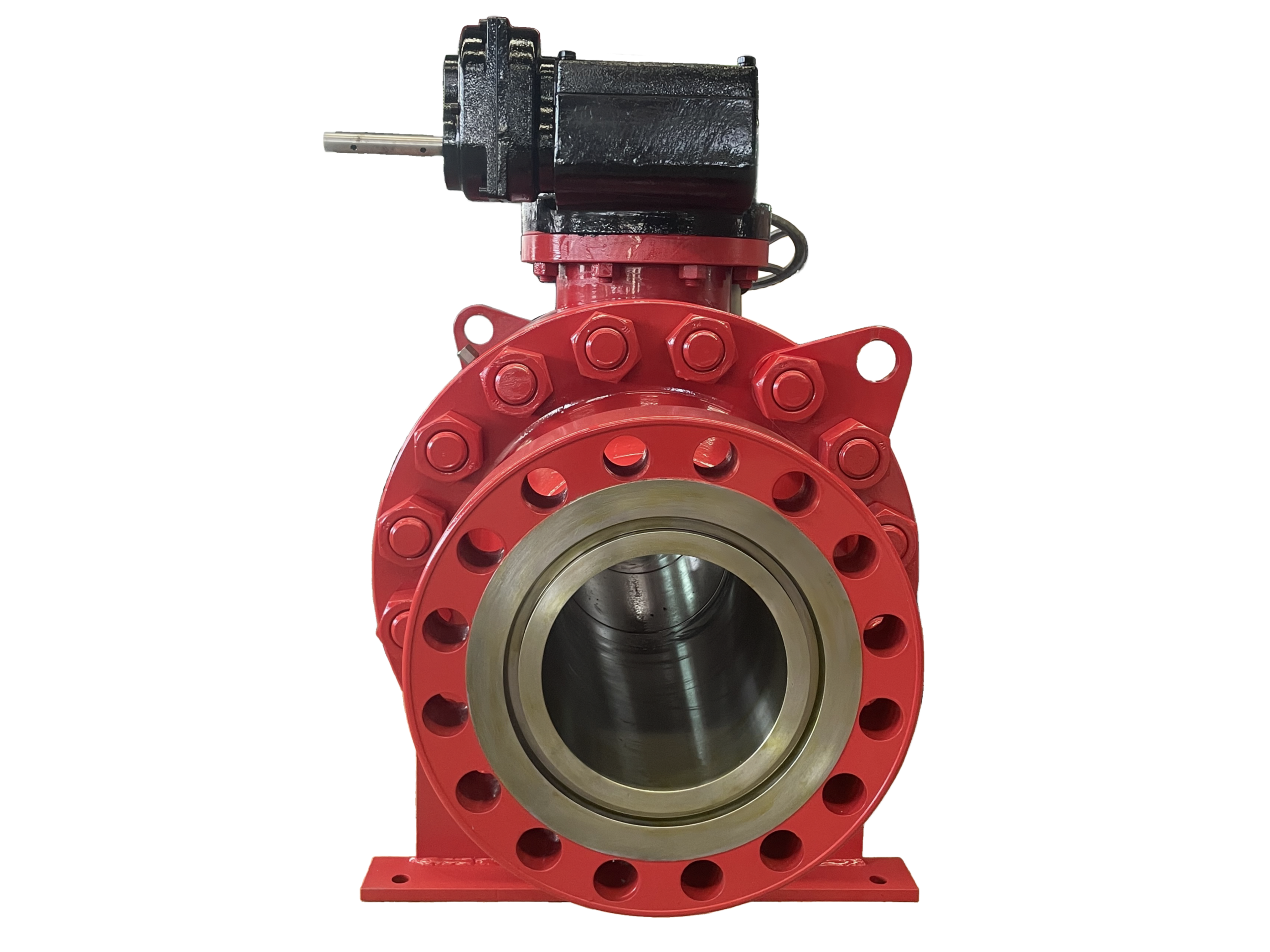
Trunnion Ball Valve Open Die Forged—10″ 2500LB SPO flange
Description
Technical Data Sheet
Open Die Forged Trunnion Ball Valve
Size: 10″ (DN250)
Pressure Class: 2500LB (ASME B16.34)
End Connection: SPO Compact Flange (API 6A Type 6B Equivalent)
1. General Description
This is a side-entry, trunnion-mounted ball valve with the body and bonnet manufactured by the open die forging process. The forging process ensures superior structural integrity and grain flow, eliminating the porosity and shrinkage defects associated with castings — particularly critical for this high-pressure, large-bore 2500LB application. The trunnion design mechanically anchors the ball via upper and lower stem/bearing assemblies, significantly reducing operating torque compared to floating ball designs and enabling reliable service under extreme pressures.
The valve is equipped with SPO (Studded Port Outlet) compact flanges, designed in accordance with API 6A Type 6B principles. SPO flanges feature a compact, lightweight profile with a metallic ring gasket seal, ideal for space-constrained offshore, subsea, and high-pressure topside applications. Since no specific body material was indicated, this data sheet presents ASTM A105N as the standard carbon steel option, with alternative materials available on request (A350 LF2 for low-temperature, A182 F316 for stainless/corrosive, F51 Duplex, etc.). The valve is designed for pipeline isolation, emergency shut-down (ESD), and critical process control in oil & gas production, refining, petrochemical, and transmission systems. Due to its size and pressure class, the valve is gear operated as standard, with ISO 5211 top works for optional pneumatic, hydraulic, or electric actuation.
2. Design Codes & Standards
Item Applicable Standard
Design & Manufacture API 6D, ASME B16.34
Face-to-Face / End-to-End API 6D, ASME B16.10
SPO Compact Flanges Per API 6A Type 6B (dimensions, bolting, ring grooves)
Pressure-Temperature Rating ASME B16.34 (Material Group 1.1 for A105N; other groups per selected material)
Inspection & Testing API 6D, API 598
Fire-Safe Design API 607 / ISO 10497 (Optional)
Forging Standard ASTM A105 / A105N (or A182, A350 per material)
Gear Operator Mounting ISO 5211
Fugitive Emissions (Optional) ISO 15848-1
3. Main Technical Specifications
Nominal Size: 10″ (DN250)
Pressure Class: Class 2500 (2500LB)
End Connection: SPO Compact Flanges, per API 6A Type 6B
Bore Type: Full Bore (standard) / Reduced Bore (optional; specify if required)
Body / Bonnet Material: ASTM A105N (Open Die Forged; standard)
Ball Material: A105 with Electroless Nickel Plating (ENP) or SS316 with Tungsten Carbide / Chrome Carbide coating for severe service
Seat Design: Single Piston Effect (SPE, self-relieving to upstream) or Double Piston Effect (DPE, bidirectional tight shutoff)
Seat Material: Devlon / PEEK / Nylon (standard for high pressure); Metal seats available on request
Stem Material: ASTM A564 17-4PH (standard) or Inconel 718 (for sour/high-temperature service)
Packing: Graphite (fire-safe), with PTFE/graphite braided combination optional
Body-Bonnet Gasket: 316L + Graphite Spiral Wound (standard); RTJ metallic ring for fire-safe / high-integrity applications
Bolting: ASTM A193 B7 / A194 2H (standard); B7M / 2HM for NACE MR0175 sour service
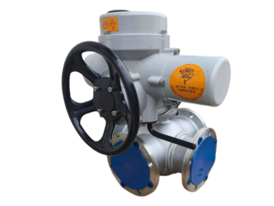
Operation: Manual Gear Operator with handwheel (standard), ISO 5211 mounting pad for pneumatic, hydraulic, or electric actuators
Service Media: Oil, gas, water, steam, condensate, hydrocarbon products, and other general industrial fluids
Temperature Range: -29 °C to +200 °C (-20 °F to +392 °F) for A105N standard; extended range possible with other material selections
Leakage Class: Zero leakage per API 6D / API 598
Design Features:
Trunnion-mounted ball with upper and lower bearings; low operating torque
Blow-out proof stem
Antistatic device (electrical continuity between ball, stem, and body)
Fire-safe certified construction (optional; API 607/ISO 10497)
Self-relieving seats (SPE) or Double Piston Effect (DPE) per project
Emergency sealant injection connections on seat and stem areas (optional)
Cavity vent / drain ports for Double Block & Bleed (DBB) verification
Locking device provision on gearbox
Open die forged body and bonnet for high integrity under extreme pressure
4. Materials of Major Parts (Standard A105N / Carbon Steel Construction)
No. Part Name Material (Standard) Standard
1 Body A105N (Open Die Forged) ASTM A105
2 Bonnet (Closure) A105N (Open Die Forged) ASTM A105
3 Ball A105 + ENP ASTM A105
4 Seat Ring Devlon / PEEK —
5 Stem A564 17-4PH ASTM A564
6 Bearings (Stem & Trunnion) SS316 + PTFE / Graphite —
7 Packing Graphite —
8 Body Gasket Spiral Wound 316L + Graphite ASME B16.20
9 Stud / Bolt A193 B7 ASTM A193
10 Nut A194 2H ASTM A194
11 Gear Operator Ductile Iron / Carbon Steel, Epoxy Painted ISO 5211
12 Handwheel Carbon Steel (Painted) —
13 Sealant Injection Fittings (Optional) SS316 with ball check valves —
*Note: For low-temperature service (down to -46 °C / -50 °F), body material changes to ASTM A350 LF2 with A320 L7 bolting. For stainless/corrosive service, ASTM A182 F316 with A193 B8M bolting. NACE MR0175 / ISO 15156 compliance for sour service available on request.*
5. Principal Dimensions (10″ 2500LB SPO Flange)
Since SPO flanges are engineered to API 6A Type 6B specifications, dimensions are governed by API 6A tables (Tables 36–38) rather than ASME B16.5. The following values are typical for a NPS 10, 2500 psi-rated SPO compact flange connection. Exact dimensions must be confirmed on the approved manufacturing drawing.
Symbol Description Value (mm) Value (inch)
L Face-to-Face / End-to-End 1270 50.0″
D SPO Flange Outer Diameter ~485 ~19.1″
D1 Bolt Circle Diameter ~394 ~15.5″
D2 Bolt Hole Diameter ~45 ~1.77″
T Flange Thickness (approx.) ~92 ~3.62″
Ring Gasket API 6B Ring Number BX-156 —
H (approx.) Centerline to Top of Gear Operator ~900 ~35.4″
H1 (approx.) Centerline to Handwheel Centre ~750 ~29.5″
ISO Pad Actuator Mounting Flange F25 / F30 —
Cv Rated Flow Coefficient (Full Bore) ~14500 —
BTO Break-to-Open Torque (approx.) 4500 – 6000 N·m —
ETC End-to-Close Torque (approx.) 3500 – 5000 N·m —
Weight Approx. Weight (valve + gear operator) ~2100 kg —
Bolt Holes Quantity & Size 12 × 1-5/8″ UNC —
*Note: Face-to-face dimension conforms to API 6D / ASME B16.10 Long Pattern for Class 2500. SPO flange dimensions are per API 6A Type 6B, NPS 10, 2500 psi rating. All dimensions are approximate and must be verified against the certified manufacturing drawing. Ring groove number (BX) is selected based on the mating companion flange. Cv value is based on published reference data for 10″ full-bore trunnion ball valves; actual value may vary by manufacturer. Operating torque values are dependent on seat material, pressure, and service conditions.*
6. Performance Tests & Inspection
Hydrostatic Shell Test: 1.5 × Class 2500 rated pressure (approx. 622 bar / 9025 psig), water, duration ≥1 minute. No leakage or permanent deformation per API 6D.
High-Pressure Hydrostatic Seat Test: 1.1 × rated pressure (approx. 456 bar / 6620 psig), water. Zero leakage permitted.
Low-Pressure Pneumatic Seat Test: 0.6 bar (6 bar g), air/nitrogen. Zero leakage.
Fire-Safe Test (Optional): Per API 607 / ISO 10497. Valve must demonstrate seat integrity before, during, and after exposure to fire at 760–980 °C.
Cryogenic / Low-Temperature Test (Optional): Per BS 6364 if LF2 or SS body material selected.
Visual & Dimensional Inspection: 100% dimensional verification. Forged body and bonnet surfaces checked for laps, cracks, and surface defects. Liquid Penetrant (PT) inspection on critical areas. Ultrasonic (UT) or Radiographic (RT) testing available per project specification.
Positive Material Identification (PMI): Full PMI on pressure-containing forgings, stem, ball, and bolting per customer requirements.
Gear Operator Functional Test: Full open-close cycle under no-load conditions. Verify smooth operation, position indicator alignment, and stop settings.
Material Certification: EN 10204 Type 3.1 certificates for all pressure-containing parts and bolting.
7. Installation & Maintenance Tips
SPO Flange Assembly: SPO compact flanges require careful attention to bolt tensioning. Use calibrated hydraulic tensioners or torque wrenches in a cross-pattern sequence. The metallic ring gasket must be correctly seated in its groove; replace the ring gasket every time the flange joint is broken. Refer to API 6A and the manufacturer’s bolt-tensioning procedure for recommended torque values.
Valve Support: At approximately 2100 kg, this valve requires independent structural supports or a dedicated valve support saddle. Never allow the valve weight to be carried solely by the SPO flange connections or the connecting pipework.
Orientation: The gear operator and actuator mounting pad should be oriented with the stem vertical. Horizontal stem orientation is acceptable only if the gearbox/actuator is independently supported.
Cavity Vent / Drain: If equipped with cavity vent/drain ports, follow DBB procedures during hydrotesting and commissioning. The body cavity must be fully depressurized before any disassembly or maintenance activity.
Seat Type Consideration: If DPE (Double Piston Effect) seats are selected, the cavity may trap pressure during thermal expansion of the trapped fluid when the valve is closed. A thermal relief valve on the body cavity is strongly recommended to prevent over-pressurization in such configurations.
Sealant Injection (if fitted): Inject only approved sealant compatible with the process fluid. Over-injection or use of incompatible lubricants can damage the seats and compromise sealing. Regular sealant top-up intervals should be established as part of the preventive maintenance program.
Gear Operator Maintenance: The gearbox is factory-lubricated. Check lubrication levels every 12 months and top up with the recommended grease grade. Verify handwheel rim-pull effort does not exceed the specified maximum.
Welding (if BW adaptors are used): If butt-weld adaptors are supplied, welding must be performed in accordance with a qualified WPS. The valve must be in the fully open position during welding to protect seats and seals from heat damage.
This technical data sheet is for selection and engineering reference only. Due to the engineered-to-order nature of SPO compact flanges and high-pressure trunnion valves, all final dimensions, flange details, torque values, weights, material selections, and pressure-temperature ratings are subject to the approved order-specific manufacturing drawing and project technical specification. The manufacturer reserves the right to modify designs without prior notice.