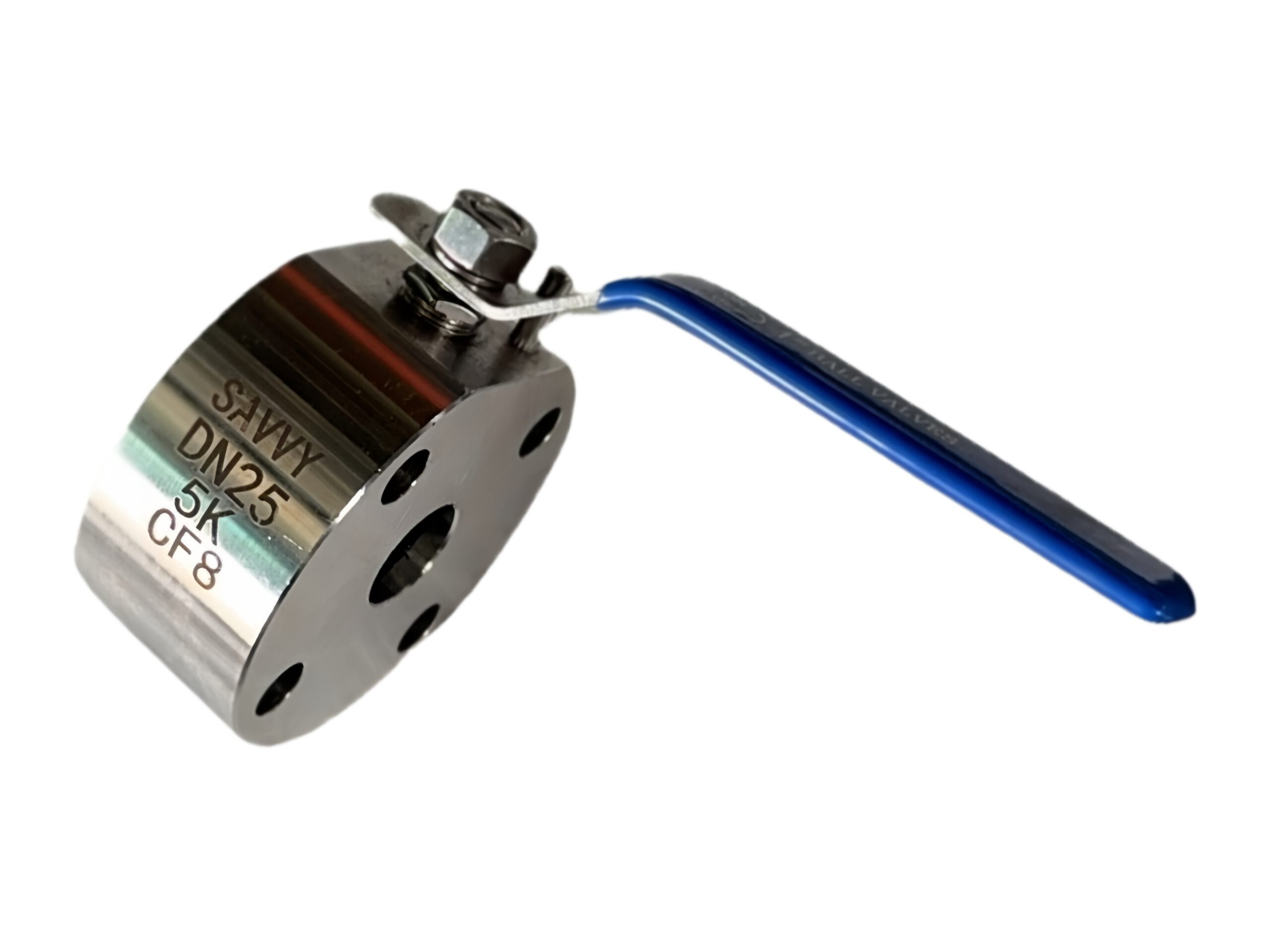
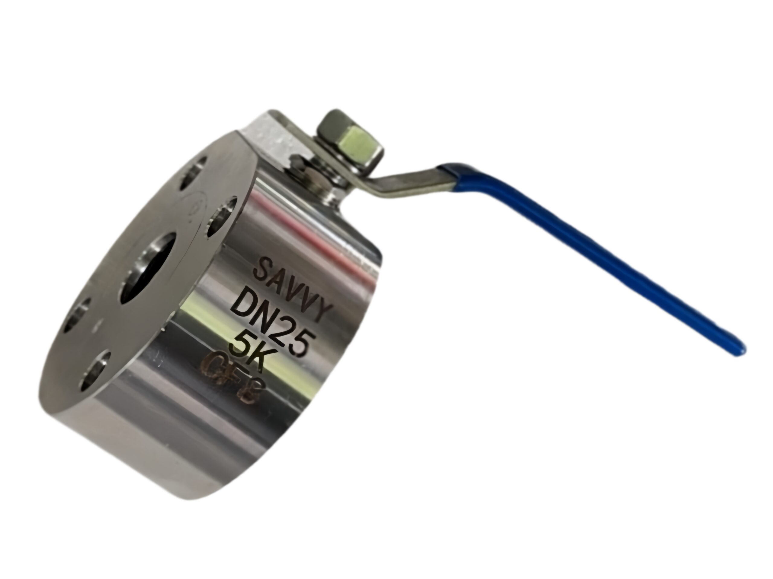
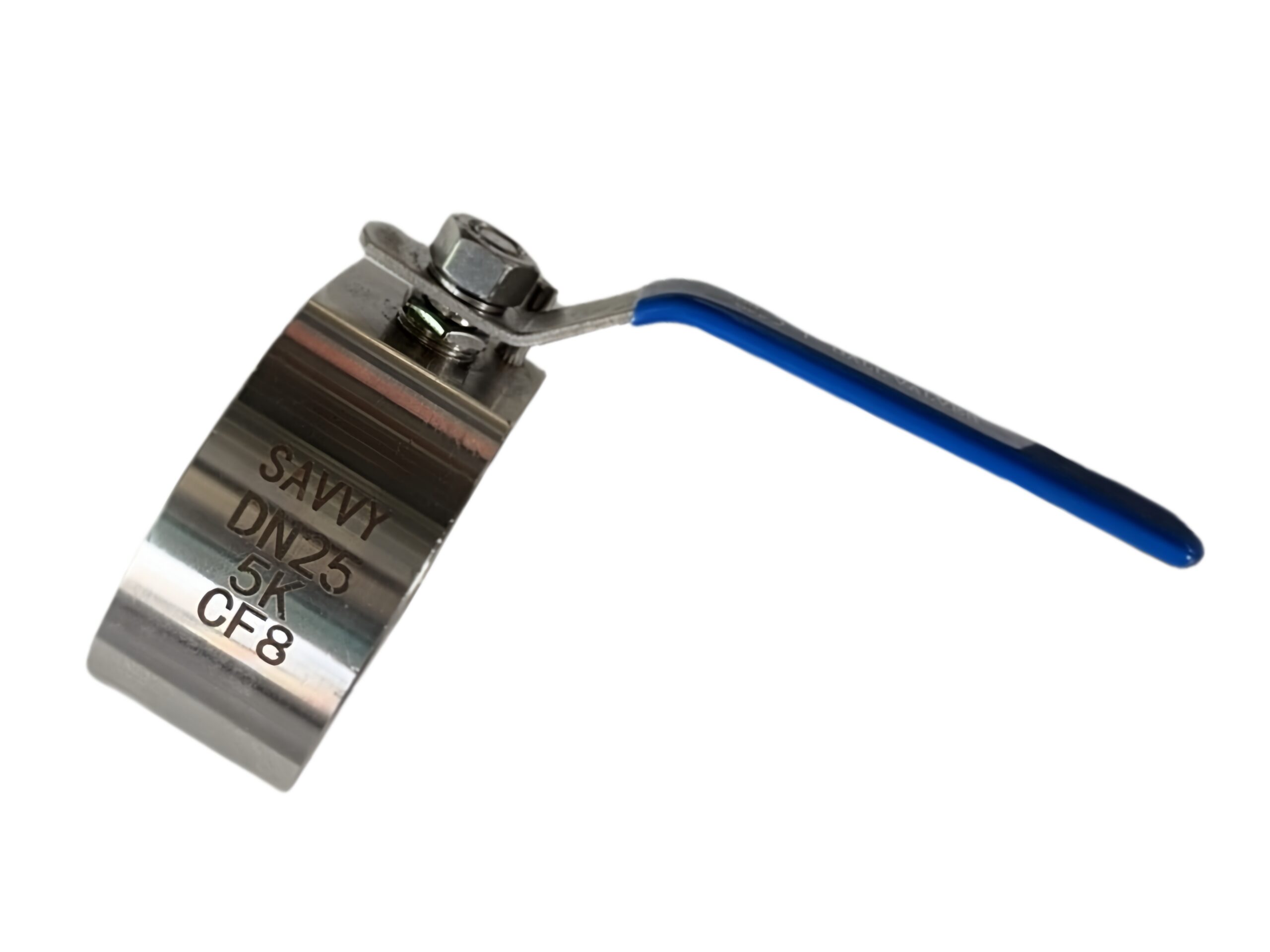
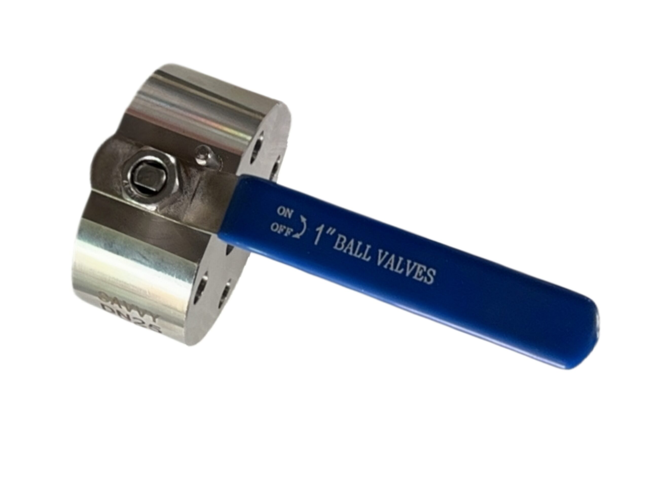
JIS 5K Wafer-Type Floating Ball Valve
Description
TECHNICAL DATA SHEET
JIS 5K Wafer-Type Floating Ball Valve
25A (DN25), Full Bore, Lever Operated
| Document Ref. | JIS5K-WAFER-BV-025-EN |
|---|---|
| Revision | 00 |
| Date | 2026-07-09 |
1. GENERAL DESCRIPTION
The JIS 5K wafer-type floating ball valve is a compact, quarter-turn isolation valve designed to be installed between two JIS 5K flanges. The wafer body eliminates the need for integral flanges, reducing weight, face-to-face dimension, and cost. The floating ball design, combined with a spring-loaded seat, provides reliable bi-directional sealing at low pressure. It is ideal for general-purpose water, oil, and gas applications in tight spaces where JIS 5K piping is used.
2. DESIGN FEATURES
-
Wafer Body: Slim, lightweight design for direct installation between JIS 5K companion flanges. No flange bolt holes on the valve body; the body is centred using the pipe bolts.
-
Full Bore (Full Port): The ball bore matches the nominal pipe diameter (25A), minimising pressure drop and allowing pigging where applicable.
-
Floating Ball: The ball is not fixed but floats against the downstream seat under media pressure, ensuring a tight seal with low operating torque.
-
Blow-Out Proof Stem: Stem with integral shoulder inserted from inside the body to prevent blow-out under pressure, conforming to international safety requirements.
-
Anti-Static Device: Conductive spring between stem and ball (or stem and body) provides electrical continuity, safely dissipating static electricity (standard on most industrial ball valves).
-
Spring-Loaded Seats: The seats are backed by a spring washer or lip design that maintains constant contact with the ball, compensating for wear and temperature fluctuations and ensuring low-pressure sealing.
-
Positive Stops: The handle body incorporates positive stops to ensure accurate 90-degree rotation and visual position indication.
3. APPLICABLE STANDARDS
| Category | Standard |
|---|---|
| Design & Manufacturing | Manufacturer’s Standard (Reference: API 608, JIS B2071) |
| Face-to-Face Dimension | Manufacturer’s Wafer Standard |
| Connection (Flange Fitting) | JIS B2220 5K (Installs between flanges) |
| Pressure-Temperature Ratings | JIS B2220 5K / Class 5K (0.5 MPa) |
| Testing & Inspection | JIS B2003 / API 598 |
| End Flange Compatibility | JIS B2220 5K, 25A (OD 95 mm, PCD 75 mm, 4 x 15 mm holes) |
4. TECHNICAL SPECIFICATIONS
| Parameter | Value |
|---|---|
| Nominal Size | 25A (DN25) |
| Nominal Pressure Rating | 5K (0.5 MPa @ 120°C) |
| Maximum Working Pressure (CWP) | 0.5 MPa (5 bar / 72.5 psi) at ambient temp. |
| Shell Test Pressure (Hydrostatic) | 0.75 MPa (1.5 x 5K) |
| Seat Leakage Test Pressure | 0.6 MPa (Air test optional) |
| Allowable Leakage Rate | API 598 / JIS B2003 acceptable rate (zero leakage for resilient seats) |
| Temperature Range (Standard) | -10 °C to +120 °C (PTFE seats) |
| Flow Direction | Bi-directional |
| Operation | Lever Handle (standard) |
| Bore Type | Full Bore (25 mm) |
5. BILL OF MATERIALS (BOM)
The standard material configuration is listed below. Alternative materials are available upon request.
| No. | Component | Material (Standard) | JIS / AISI Grade |
|---|---|---|---|
| 1 | Body (Wafer Type) | Stainless Steel | SCS13 (ASTM A351 CF8 / 304) |
| 2 | End Piece / Insert | Stainless Steel | SCS13 / SUS304 |
| 3 | Ball | Stainless Steel | SUS304 (AISI 304) |
| 4 | Stem | Stainless Steel | SUS304 |
| 5 | Seat Ring | Virgin PTFE | — |
| 6 | Body Gasket / Seal | PTFE | — |
| 7 | Stem Thrust Washer | PTFE | — |
| 8 | Stem O-Ring / Packing | FKM (Viton) / NBR | — |
| 9 | Anti-Static Spring | Stainless Steel | SUS301 |
| 10 | Handle / Lever | Stainless Steel | SUS304 |
| 11 | Handle Sleeve | PVC (Blue/Black) | — |
| 12 | Retaining Nut / Stop Pin | Stainless Steel | SUS304 |
Note: For corrosive fluid applications, SCS14 (316) body and SUS316 ball/stem are available. For steam or high-temperature use, specify reinforced PTFE or metal seated options (consult factory).
6. DIMENSIONS & WEIGHTS (25A / DN25)
| Symbol | Description | Dimension |
|---|---|---|
| L | Face-to-Face (Installed between flanges) | 44 mm |
| D | Flange O.D. fitting (Body diameter) | 95 mm |
| H | Centre of pipe to top of lever (Valve open) | 105 mm |
| W | Lever Length | 130 mm |
| M | Required stud bolt length (approx.) | 120 mm (M12 x 2 sets) |
| Weight | Approximate | 0.8 kg |
Important: The valve body is sandwiched between two JIS 5K 25A standard flanges (OD 95 mm, PCD 75 mm). Use full-length stud bolts and tighten evenly to the recommended torque. No gaskets are required between the valve and flanges for PTFE body seals, but flange gaskets may be used if preferred.
7. TESTING & INSPECTION
Every valve is pressure tested according to JIS B2003:
-
Shell Test: 0.75 MPa (7.5 bar) water for a minimum of 60 seconds. No visible leakage permitted.
-
Backseat Test (optional): Not applicable (floating ball design; blow-out proof verified by design).
-
Seat Leakage Test: 0.6 MPa (6 bar) air or water. For PTFE seated valves, allowable leakage rate as per API 598 (typically zero leakage with water).
-
Additional Tests: Anti-static continuity test, handle torque verification, material PMI (on request).
8. PRESSURE-TEMPERATURE RATING (for PTFE seats)
The maximum working pressure is subject to temperature. As a guide for PTFE seated valves:
| Temperature (°C) | Max. Pressure (MPa) |
|---|---|
| -10 to +50 | 0.50 (5K) |
| 80 | 0.45 |
| 100 | 0.40 |
| 120 | 0.35 |
For continuous operation above 120°C, PTFE seats are not recommended. Please consult the factory for alternative seat materials.
9. OPERATING TORQUE
Approximate breakaway torque for clean water service at 0.5 MPa differential pressure: 4 – 6 N·m.
A standard lever (130 mm) provides sufficient mechanical advantage for manual operation. For actuated versions (electric/pneumatic), please specify the required actuator flange and torque.
10. ACCESSORIES & OPTIONS
-
Lever Lock: Padlockable lever handle in open/closed position.
-
Extended Stem: For insulated piping or buried service (indicate extension length).
-
Actuator Mounting Flange: ISO 5211 F03 or F04 direct mount pad (body machined accordingly).
-
Limit Switch Box: Mechanical or proximity type for remote position feedback.
-
Cavity Filler: PTFE cavity filler to eliminate media entrapment in the body cavity (for hygienic or viscous services).
-
Material Upgrades: SCS14 (316) body/trim, Hastelloy, Duplex stainless steel, etc.
11. NOTES
-
Ensure the pipeline is clean and free from debris before installation to prevent seat damage.
-
The wafer valve is designed for installation between JIS 5K flanges only. Flange dimensions must conform to JIS B2220 5K. Do not attempt to install between ASME/EN flanges without dimensional verification.
-
For dead-end service (valve at end of pipe with blank flange), consult factory for maximum allowable differential pressure.
-
This data sheet provides standard product information. Certified dimensioned drawings and material test certificates (EN 10204 3.1) are available upon request.
The manufacturer reserves the right to modify specifications in the interest of product improvement. All dimensions are nominal and subject to manufacturing tolerances.