DIN3202 F4 Short Pattern Ball Valve
Description
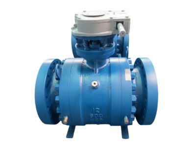
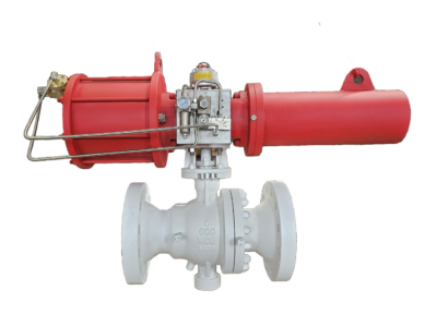
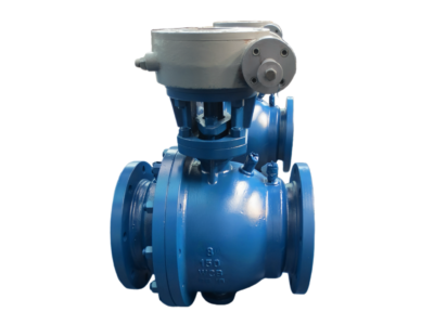
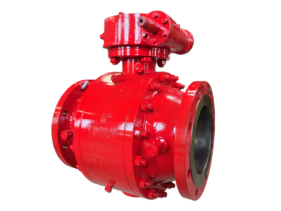
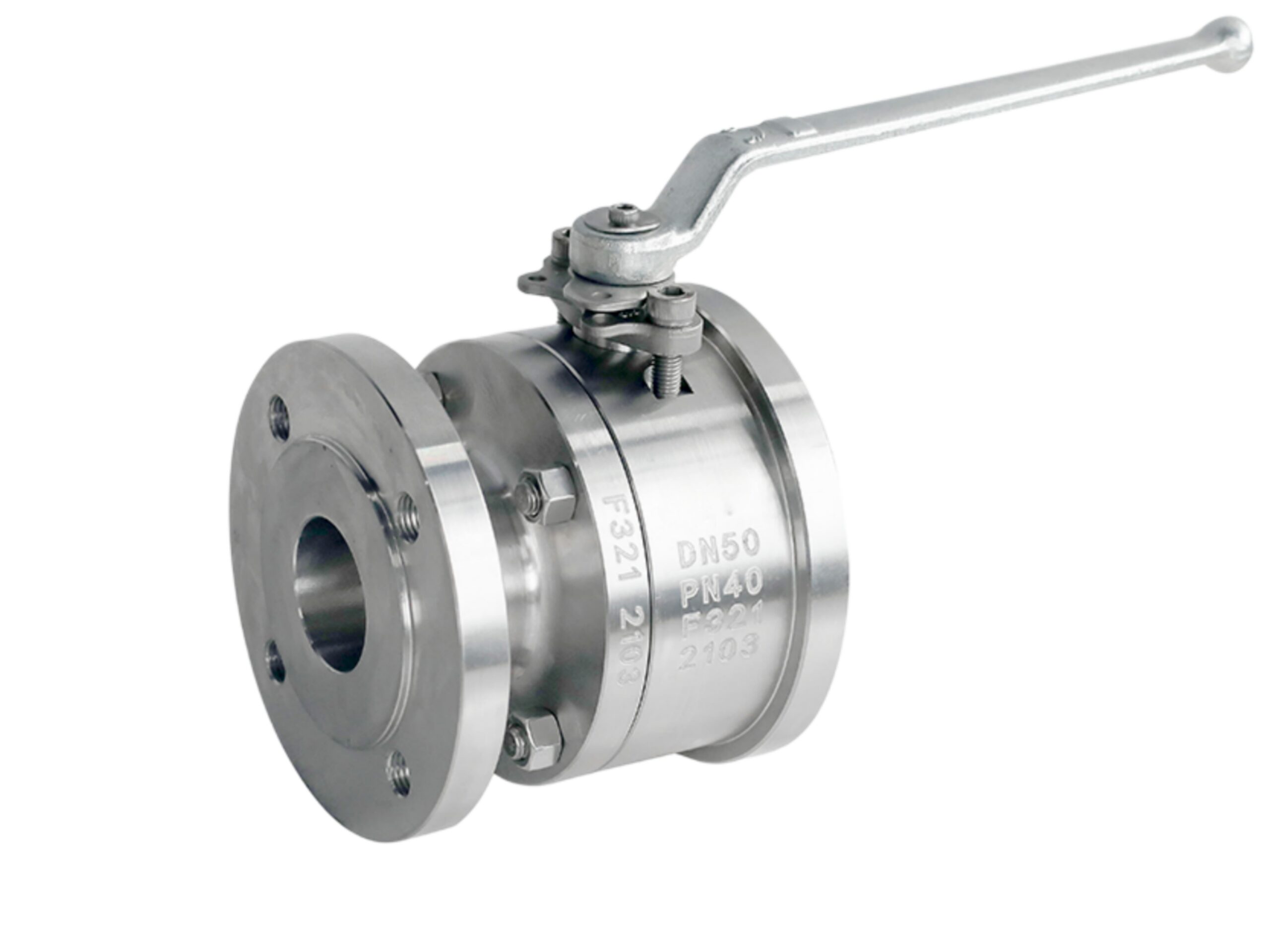
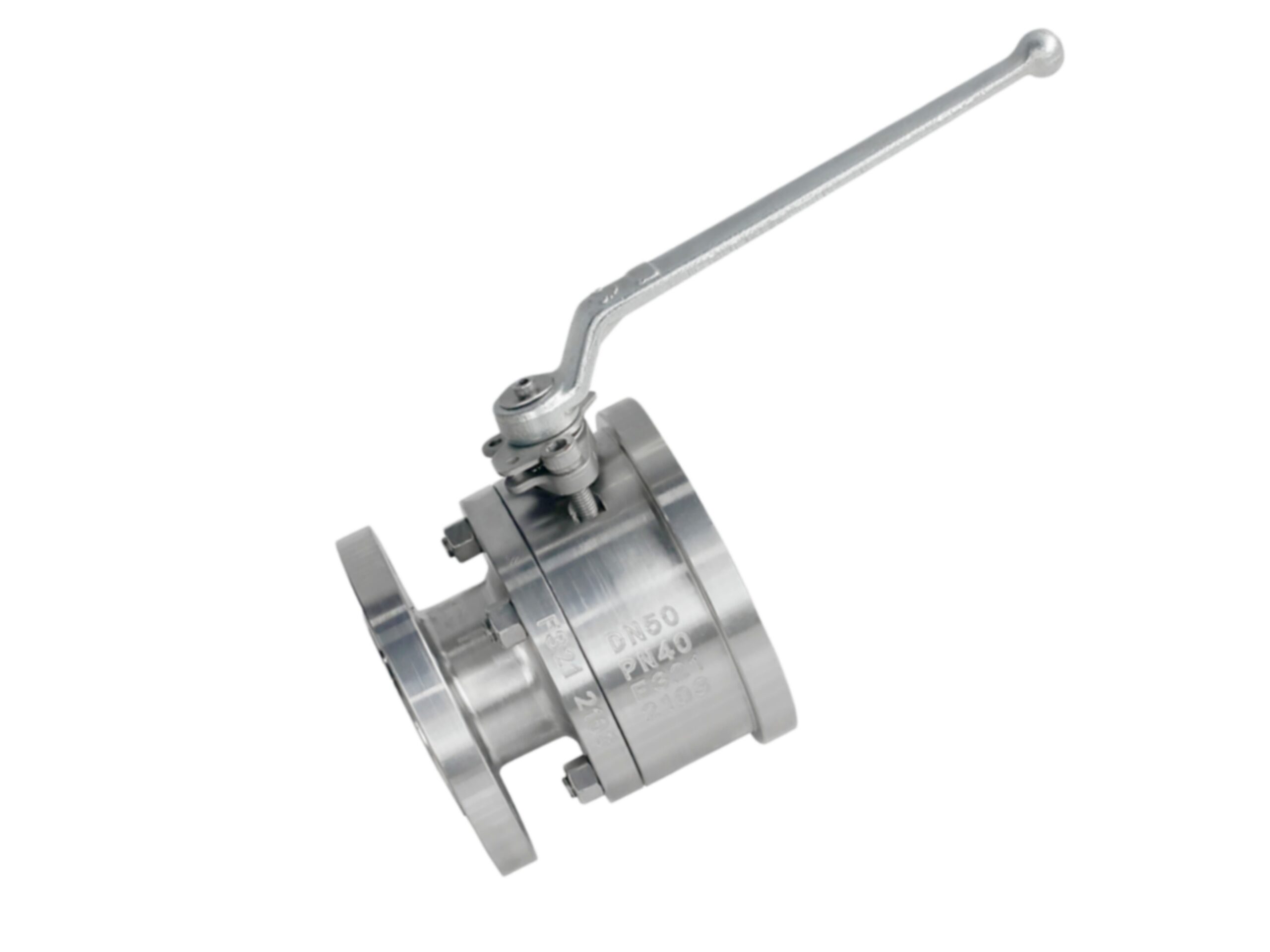
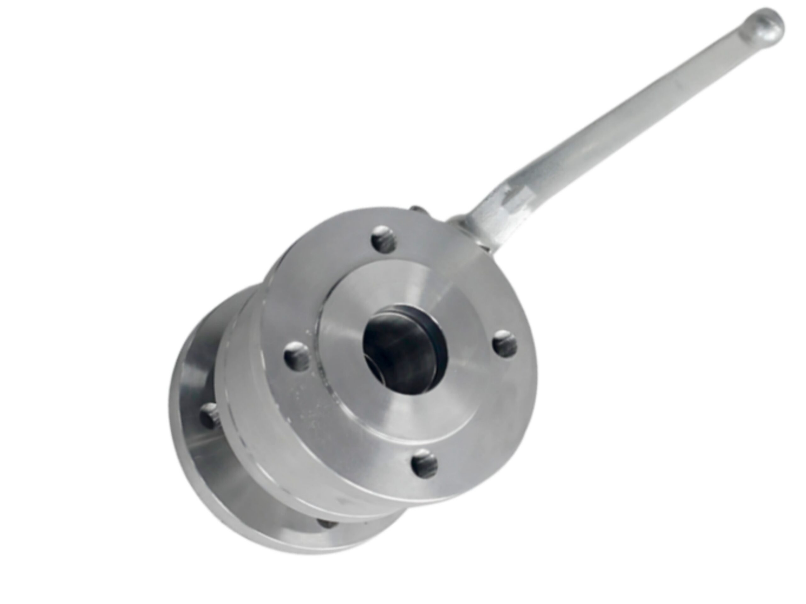
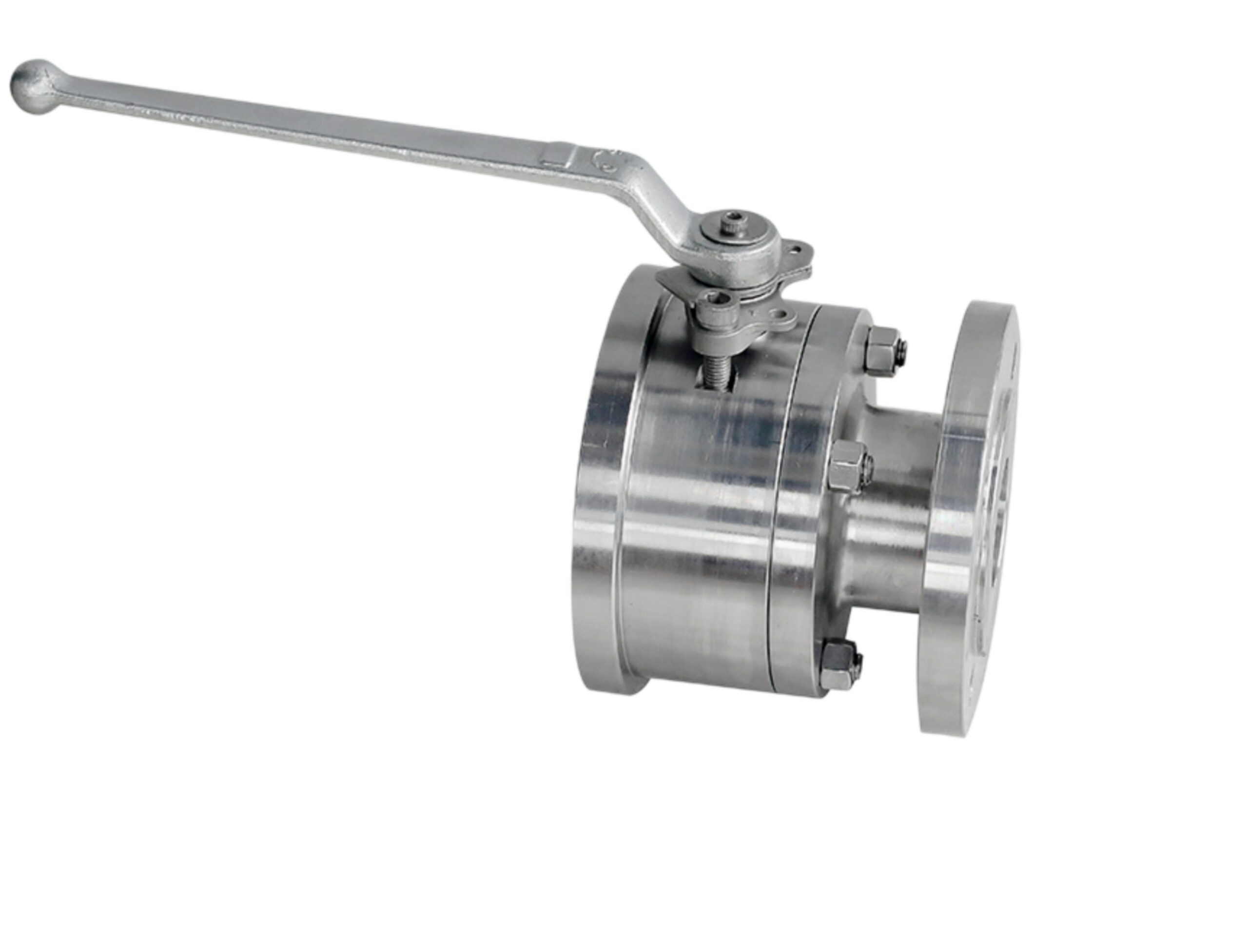
DIN 3202 F4 Short Pattern Ball Valve – F321 Material, Floating Ball
Model: BV-F4-F321-FL
Product Description: Two-piece bolted-body, side-entry floating ball valve with short face-to-face dimension in accordance with DIN 3202 F4. Manufactured from ASTM A182 F321 (titanium-stabilized austenitic stainless steel), suitable for corrosive and elevated temperature services where intergranular corrosion resistance is required.
1. Main Design Codes and Standards
| Item | Standard / Code |
|---|---|
| Valve Design & Dimensions | ISO 17292, BS 5351, ASME B16.34 |
| Face-to-Face | DIN 3202 Series F4 (Short Pattern) |
| Flanged Ends | EN 1092-1 PN 40 / ASME B16.5 Class 300 |
| Pressure-Temperature Ratings | EN 1092-1 Material Group 14E0 (1.4541) / ASME B16.34 Group 2.2 |
| Testing & Inspection | ISO 5208, API 598 |
| Fire-Safe Design (Optional) | API 607, ISO 10497 |
| Fugitive Emissions (Optional) | ISO 15848-1 |
| Anti-Static Design | Per ISO 17292 / API 608 (electrical continuity between ball, stem and body) |
2. Main Technical Parameters
| Parameter | Specification |
|---|---|
| Available Size Range | DN15 (1/2″) to DN200 (8″) – Detailed data provided for DN50 |
| Pressure Rating | PN40 (Class 300 equivalent) |
| End Connection | Flanged EN 1092-1 Type B1 (RF) PN40 / ASME B16.5 RF |
| Body Construction | Two-piece, bolted body, side entry |
| Ball Type | Floating ball, full or reduced bore |
| Operation | Lever handle (up to DN100); gear operator optional for larger sizes |
| Flow Direction | Bi-directional, bubble-tight shut-off |
| Blow-out Proof Stem | Yes, internally inserted stem with integral shoulder |
3. Pressure-Temperature Ratings (Body Material ASTM A182 F321)
Based on EN 1092-1 for material 1.4541 (F321) – Class PN40. Ratings below show maximum allowable non-shock pressures (bar) for the metal body. Actual operating limits may be further restricted by seat material.
| Temperature (°C) | Max. Working Pressure (bar) |
|---|---|
| -60 to 50 | 40.0 |
| 100 | 36.0 |
| 150 | 32.8 |
| 200 | 30.0 |
| 250 | 27.6 |
| 300 | 25.5 |
| 350 | 23.8 |
| 400 | 22.2 |
| 450 | 20.8 |
| 500 | 19.5 |
Note: The standard PTFE seat limits the continuous operating temperature to approximately 180 °C. For higher temperatures, reinforced PTFE (RTFE) or metal/graphite seats are available, extending the limit up to 300 °C or 500 °C respectively. Contact manufacturer for seat-specific P-T curves.
4. Materials of Main Parts
| No. | Part Name | Material | Remarks |
|---|---|---|---|
| 1 | Body & End Piece | ASTM A182 F321 (UNS S32100) | Titanium-stabilized, fully solution annealed |
| 2 | Ball | ASTM A182 F321 / SS321 + ENP* | Electroless nickel plating (ENP) optional for wear resistance; solid F321 also available |
| 3 | Stem | ASTM A182 F321 | Anti-blowout design, ground and polished |
| 4 | Body Seals / Gaskets | PTFE / Graphite | Service-dependent |
| 5 | Ball Seats | Virgin PTFE (standard) | RTFE, PEEK, or metal-seated on request |
| 6 | Stem Sealing / Packing | PTFE V-rings / Graphite | Adjustable packing gland |
| 7 | Stem Thrust Washer | PTFE / Filled PTFE | Low friction, long life |
| 8 | Bolting | ASTM A193 B8T (321 SS) / A194 Gr.8T | Fully stainless steel bolting for corrosion resistance |
| 9 | Handle / Lever | SS304 with PVC grip | Lockable handle design optional |
| 10 | Anti-Static Spring | SS316 | Ensures continuity per ISO 17292 |
ENP = Electroless Nickel Plating.
5. Dimensions & Weight – Typical Example (DN50 / 2″ PN40, Short Pattern F4)
| Parameter | Dimension (mm) | Remarks |
|---|---|---|
| Face-to-Face (L) | 230 | DIN 3202 Series F4 Short |
| Overall Height (H) – Centreline to Top | ~125 | Lever open position |
| Lever Length (W) | ~200 | |
| Flange Size | DN50, PN40 RF (EN 1092-1) | Drilling matches PN40 and Class 300 |
| Bore | Full Bore (38 mm) / Reduced Bore (on request) | Full bore as standard for DN50 |
| Approx. Weight | 12 kg | Manual lever configuration |
Additional face-to-face dimensions per DIN 3202 F4:
-
DN15: 130 mm
-
DN20: 150 mm
-
DN25: 160 mm
-
DN32: 180 mm
-
DN40: 200 mm
-
DN65: 290 mm
-
DN80: 310 mm
-
DN100: 350 mm
Refer to certified drawings for exact dimensions and other pressure classes.
6. Performance Testing
| Test Item | Test Medium | Test Pressure | Acceptance Criteria |
|---|---|---|---|
| Shell Hydrostatic | Water | 60 bar (1.5 × PN) | No visible leakage or deformation |
| Seat Leakage (High Pressure) | Water | 44 bar (1.1 × PN) | Rate A per ISO 5208 (zero leakage for soft seats) |
| Seat Leakage (Low Pressure) | Air / Nitrogen | 6 bar | Zero bubble leakage |
| Backseat / Stem Seal Test | Water | 44 bar | No leakage at stem/gland |
| Anti-Static Test | – | DC resistance ≤10 Ω | ISO 17292 |
| Fire-Safe Test (optional) | – | Per API 607 | Passes fire exposure and leakage tests |
7. Floating Ball & Sealing Characteristics
-
Floating Ball Design: The ball is not fixed but is free to move axially; line pressure pushes the ball against the downstream seat, ensuring a tight seal at low and high pressures.
-
Bi-Directional Sealing: Equipped with twin seats; effective shut-off in both flow directions.
-
Low Operating Torque: Optimized stem and seat geometry reduces breakaway torque; lever operation remains easy up to DN100.
-
Cavity Pressure Relief: A pressure relief hole in the ball (standard on liquid service) prevents over-pressurization of the body cavity due to thermal expansion.
-
Stem Design: Blow-out proof single-piece stem with integral collar; provides secondary metal-to-metal back-up sealing in the fully open position.
8. Application Scope
-
Suitable Media: Petrochemicals, acids, alkalis, heat transfer fluids, chlorinated solvents, steam, hot gases, and other corrosive or high-purity media requiring 321 stainless steel.
-
Temperature Range: -60 °C to 500 °C (body material capability; seat material will set the practical limit).
-
Key Features:
-
DIN 3202 F4 short face-to-face saves installation space and weight.
-
F321 material stabilised against intergranular corrosion, ideal for continuous service between 400 °C and 800 °C where sensitisation may occur.
-
Two-piece bolted body allows easy maintenance and seat replacement inline.
-
Full-bore option provides minimal pressure drop and allows pigging.
-
Standard anti-static and blow-out proof stem enhance safety in hydrocarbon service.
-
9. Optional Configurations & Accessories
-
Seat Materials: RTFE (up to 220 °C), PEEK (up to 260 °C), metal/graphite (up to 500 °C).
-
Fire-Safe Package: API 607 certified with graphite body seals and secondary metal seats.
-
Oxygen Service Cleaning: Degreased and inspected per CGA G-4.1 or ASTM G93.
-
Actuation: ISO 5211 top mounting pad for pneumatic or electric actuators (bracket and coupling included).
-
Locking Device: Lever lockable in open/closed position.
-
Limit Switches & Positioners: NAMUR interface available.
-
Extended Stem: For insulated pipelines or buried services.
Disclaimer: This technical data sheet is compiled as an engineering reference based on applicable industrial standards and typical design configurations. Specific product performance, dimensions, and materials must be validated against the manufacturer’s official certified documentation and drawings prior to application or procurement.