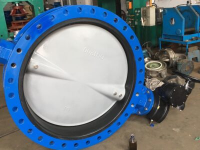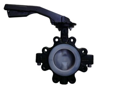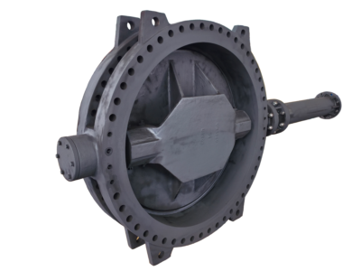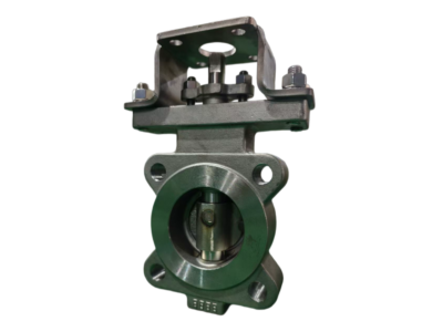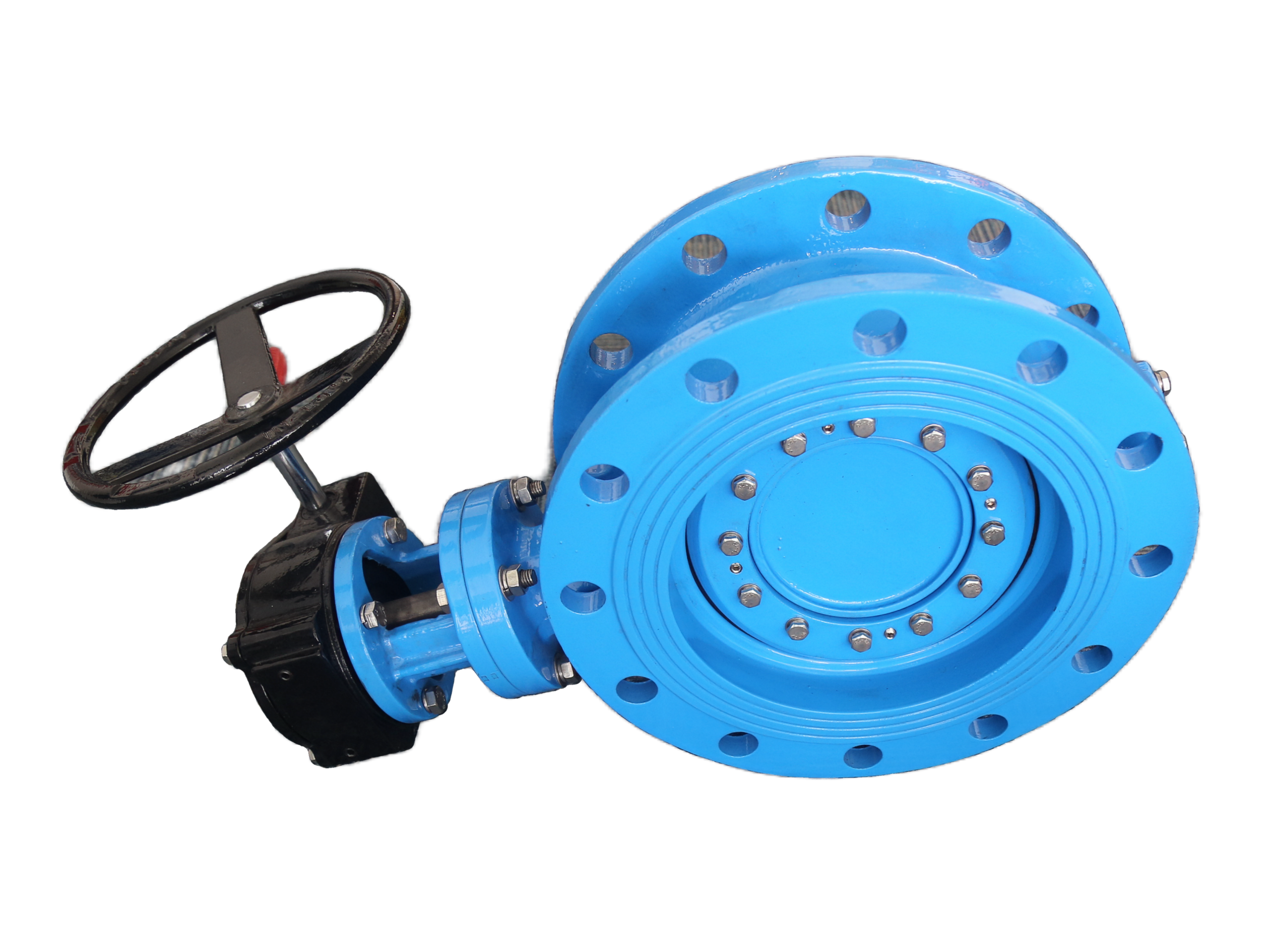
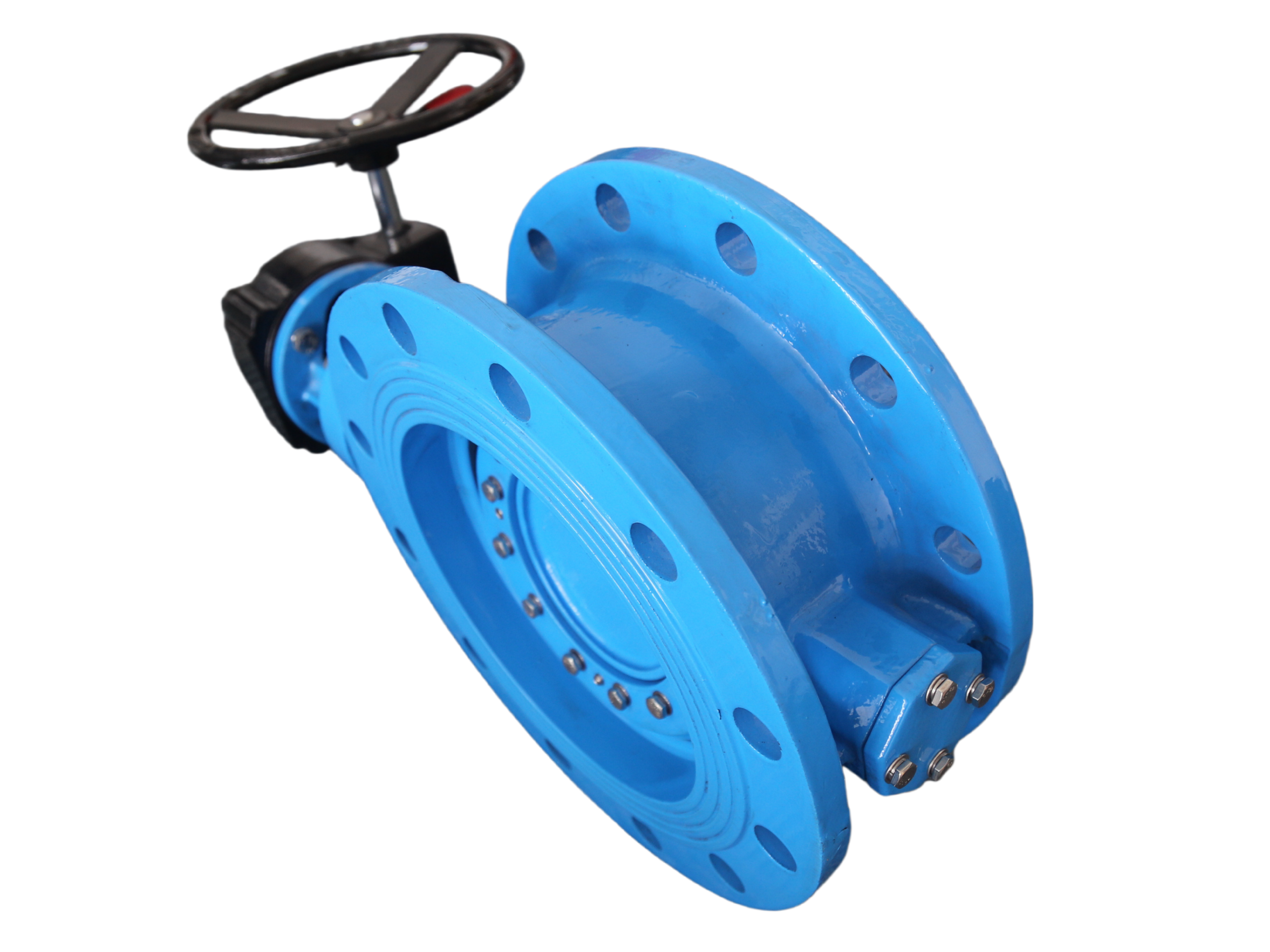
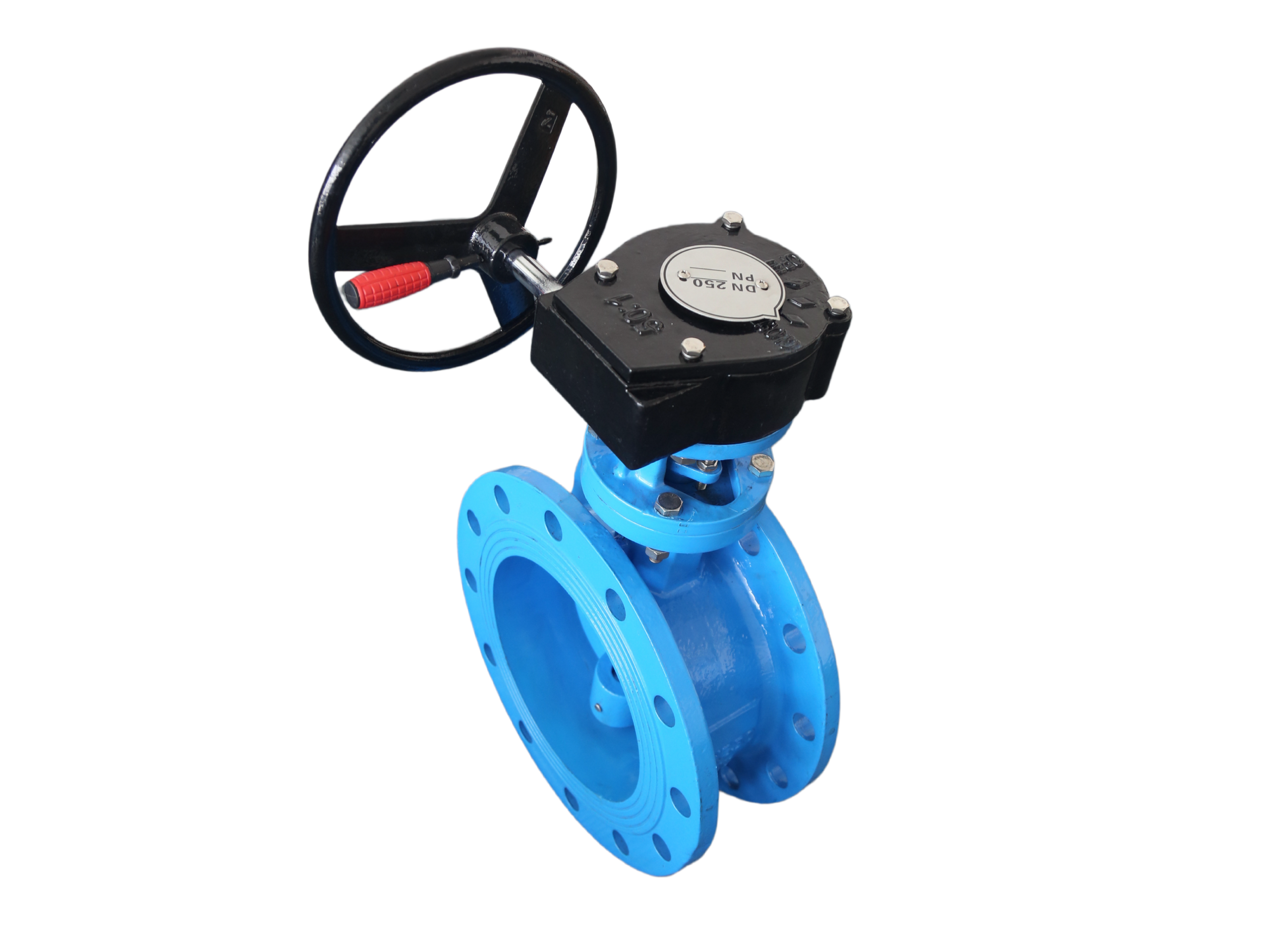
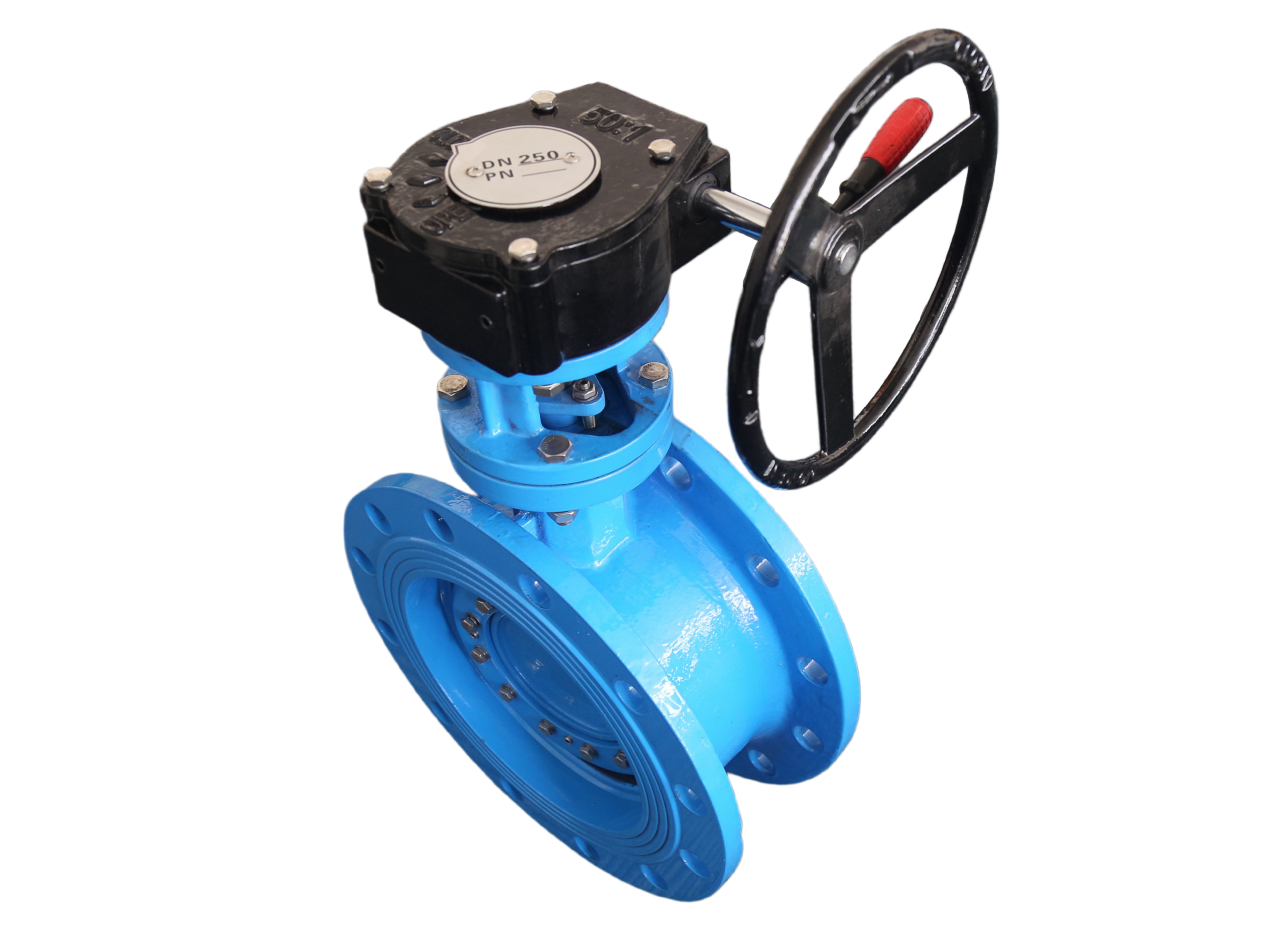
Typical Rubber Seated Double Offset Butterfly Valve
Description
DOUBLE OFFSET RUBBER SEATED BUTTERFLY VALVE – TECHNICAL DATA SHEET
(Ductile Iron Body & Disc / Rubber Seat)
Project Name: ________________________
Item No.: ________________________
Tag No.: ________________________
Quantity: ________________________
Date: ________________________
1. VALVE GENERAL INFORMATION
| Parameter | Specification |
|---|---|
| Valve Type | Double Offset Butterfly Valve (High Performance) |
| Body Construction | Wafer / Lug / Flanged (as required) |
| Body Material | Ductile Iron (ASTM A536 Grade 65-45-12 / GGG-50) |
| Disc Material | Ductile Iron (ASTM A536 Grade 65-45-12 / GGG-50) + Electroless Nickel Plating (ENP) |
| Seat Material | EPDM / NBR / Viton (Bonded or Replaceable Cartridge type) |
| Stem Material | Stainless Steel (AISI 416 / 431 / 304 / 316) |
| Bushings / Bearings | Self-lubricating PTFE / Bronze-backed PTFE |
| Nominal Size (DN / NPS) | 2″ – 48″ (DN50 – DN1200) |
| Pressure Rating | Class 125 / Class 150 / PN10 / PN16 / PN25 |
| End Connection | Wafer, Lug, or Flanged (RF / FF) |
| Design Standard | API 609 / ASME B16.34 / EN 593 / ISO 5752 |
| Face-to-Face Standard | API 609, ISO 5752 Series 20 (Short) / Series 13 (Long) |
| Flange Drilling Standard | ASME B16.5 / ASME B16.47 / EN 1092 / JIS |
| Inspection & Test Standard | API 598 / ISO 5208 / EN 12266-1 |
| Temperature Range | -30°C to +120°C (EPDM), -10°C to +80°C (NBR), -15°C to +150°C (Viton) |
2. MATERIALS OF CONSTRUCTION
| No. | Component | Material | Remarks |
|---|---|---|---|
| 1 | Body | Ductile Iron (ASTM A536 65-45-12 / EN-GJS-450-10) | Epoxy coated (internal/external, min. 300 μm) |
| 2 | Disc | Ductile Iron (ASTM A536) + Electroless Nickel Plating (ENP) | Corrosion resistant, smooth surface |
| 3 | Seat | EPDM Rubber (or NBR/Viton) | Bonded-in or replaceable cartridge design |
| 4 | Upper Stem | Stainless Steel (AISI 416 / 431) | Anti-blowout design |
| 5 | Lower Stem | Stainless Steel (AISI 416 / 431) | — |
| 6 | Bearings / Bushings | PTFE / Bronze | For low friction and wear resistance |
| 7 | Thrust Washer | PTFE / Stainless Steel | — |
| 8 | O-Rings / Seals | EPDM / Viton | For stem sealing |
| 9 | Nameplate | Stainless Steel / Aluminum | — |
| 10 | Fasteners | Stainless Steel (304) | For lug/flanged types |
Alternative materials available upon request (e.g., Super Duplex, Alloy 20, etc.).
3. DESIGN FEATURES (DOUBLE OFFSET)
| Feature | Description | Benefit |
|---|---|---|
| Double Offset Geometry | Two independent offsets: (1) stem axis offset from disc centerline; (2) disc centerline offset from pipe centerline | Cam-like sealing action minimizes rubbing, reduces torque and wear |
| Rubber Seat | Resilient elastomer seat (EPDM/NBR/Viton) provides bubble-tight shut-off | Zero leakage even at low pressure |
| Nickel Plated Disc | Electroless nickel plating gives excellent corrosion and erosion resistance | Prolongs service life in water/wastewater |
| Cartridge or Bonded Seat | Seat can be vulcanized to body or replaceable without removing actuator | Easy maintenance |
| Long Service Life | Double offset design eliminates “jamming” of disc against seat | Lower operating torque and longer seat life |
| Bi-directional Shut-off | Seals equally well in both flow directions | Flexible installation |
| Top Entry / Anti-blowout Stem | Stem retained with anti-blowout ring | Safety in case of internal pressure |
| Low Flow Resistance | Disc opens to 90° with minimal obstruction | Low pressure drop |
4. APPLICABLE STANDARDS & SPECIFICATIONS
| Item | Standard |
|---|---|
| Design & Manufacturing | API 609, ASME B16.34, EN 593 |
| Face-to-Face Dimensions | API 609, ISO 5752 Series 20 / 13 |
| Flange Connection | ASME B16.5, B16.47, EN 1092-2, JIS B2220 |
| Inspection & Testing | API 598, ISO 5208, EN 12266-1 |
| Coating | WRAS approved fusion-bonded epoxy, min. 300 μm |
5. PRESSURE TEST (PER API 598)
| Test Type | Description |
|---|---|
| Shell (Hydrostatic) | 1.5 × rated pressure for Class 150 / PN16 |
| High Pressure Seat Test | 1.1 × rated pressure (water) |
| Low Pressure Seat Test | 5–6 bar (air or nitrogen) |
| Leakage Rate | Zero (bubble-tight) per ISO 5208 Rate A |
100% hydrostatic shell and seat tests, plus low pressure air test performed on every valve.
6. PERFORMANCE DATA
| Parameter | Specification |
|---|---|
| Service Medium | Water, Wastewater, Oil, Gas, Mild Chemicals (depending on elastomer) |
| Design Temperature | See seat material selection |
| Max. Working Pressure | Up to 25 bar (PN25) / Class 150 |
| Leakage Class | ISO 5208 Rate A / API 598 Class A (bubble-tight) |
| Operation Torque | Low due to double offset design |
| Installation Position | Any (horizontal, vertical, inclined) |
| Flow Direction | Bi-directional (marked on body) |
| Cracking Pressure | N/A (quarter-turn valve) |
7. DIMENSIONS (Reference – Wafer Type, API 609 Short Pattern, Class 150)
| DN (mm) | NPS (inch) | Face-to-Face L (mm) | Flange ØD (mm) – Drilling |
|---|---|---|---|
| 50 | 2″ | 43 | 4 × 19 mm on 125 mm BC |
| 80 | 3″ | 46 | 4 × 19 mm on 160 mm BC |
| 100 | 4″ | 52 | 8 × 19 mm on 190 mm BC |
| 150 | 6″ | 56 | 8 × 22 mm on 250 mm BC |
| 200 | 8″ | 60 | 8 × 22 mm on 320 mm BC |
| 250 | 10″ | 68 | 12 × 26 mm on 385 mm BC |
| 300 | 12″ | 78 | 12 × 26 mm on 450 mm BC |
| 350 | 14″ | 78 | 12 × 29 mm on 510 mm BC |
| 400 | 16″ | 102 | 16 × 29 mm on 575 mm BC |
| 450 | 18″ | 114 | 16 × 32 mm on 635 mm BC |
| 500 | 20″ | 127 | 20 × 32 mm on 700 mm BC |
For lugged or flanged types and other pressure ratings, please refer to API 609 or contact the manufacturer.
8. OPTIONAL UPGRADES
| Option | Description |
|---|---|
| Seat Material | NBR, Viton, Silicone, PTFE (for higher temperatures) |
| Disc Material | CF8, CF8M, 2205, 2507, Aluminum Bronze, etc. |
| Body Material | Cast Iron, Carbon Steel WCB, Stainless Steel |
| Stem Material | AISI 304, 316, 17-4PH, Inconel |
| End Connection | Lugged or Flanged (RF, FF, RTJ) |
| Coating | Fusion-bonded epoxy (WRAS approved), NACE compliant |
| Operation | Lever, gearbox, electric/pneumatic actuator |
9. QUALITY CONTROL
-
100% chemical analysis and mechanical testing on all heat numbers
-
100% DPT (dye penetrant) on castings; MT/UT/RT available as requested
-
100% hydrostatic shell and seat test, plus low pressure air seat test
-
All coatings thickness checked with calibrated gauges
10. WARRANTY
12 months service life at minimum; free spares and maintenance instruction provided when required.
This technical data sheet is for reference purposes only. All specifications are subject to change without prior notice. For specific project requirements, please consult the manufacturer.