API 6A FLS Gate Valves —2-1/16″ 5000psi
Description
Technical Data Sheet
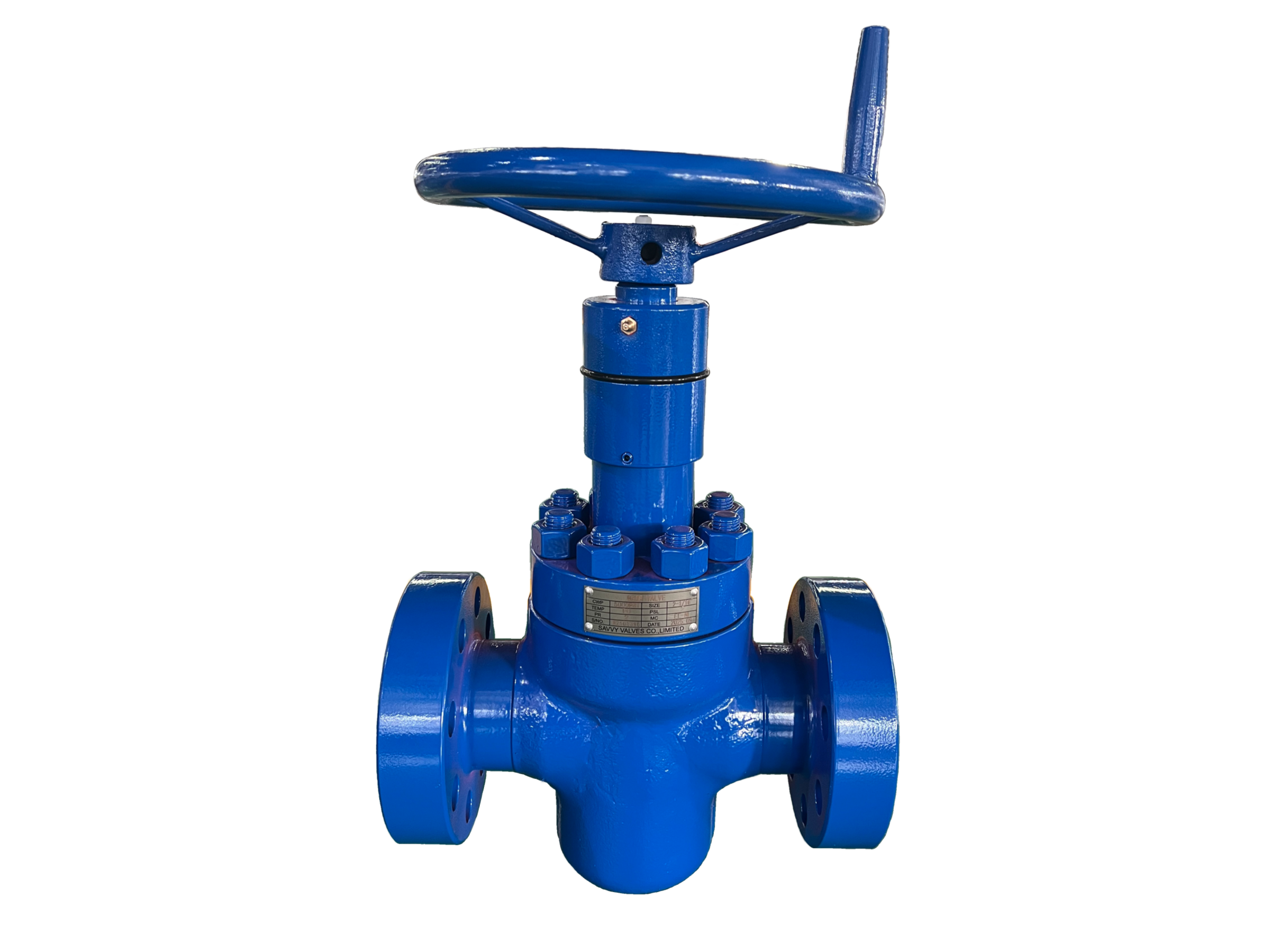
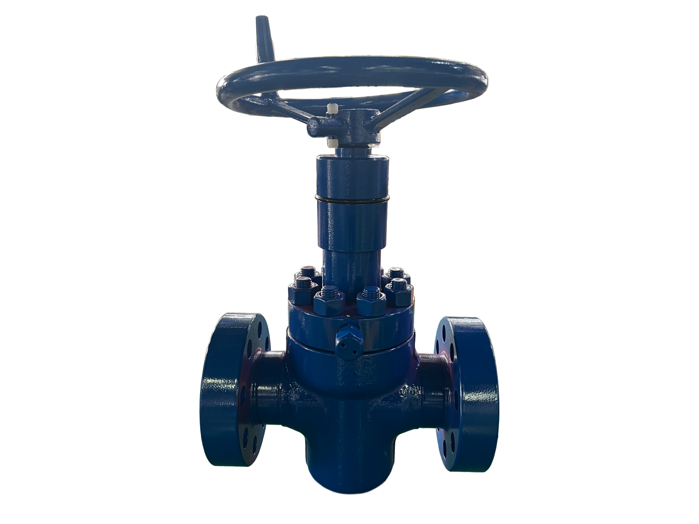
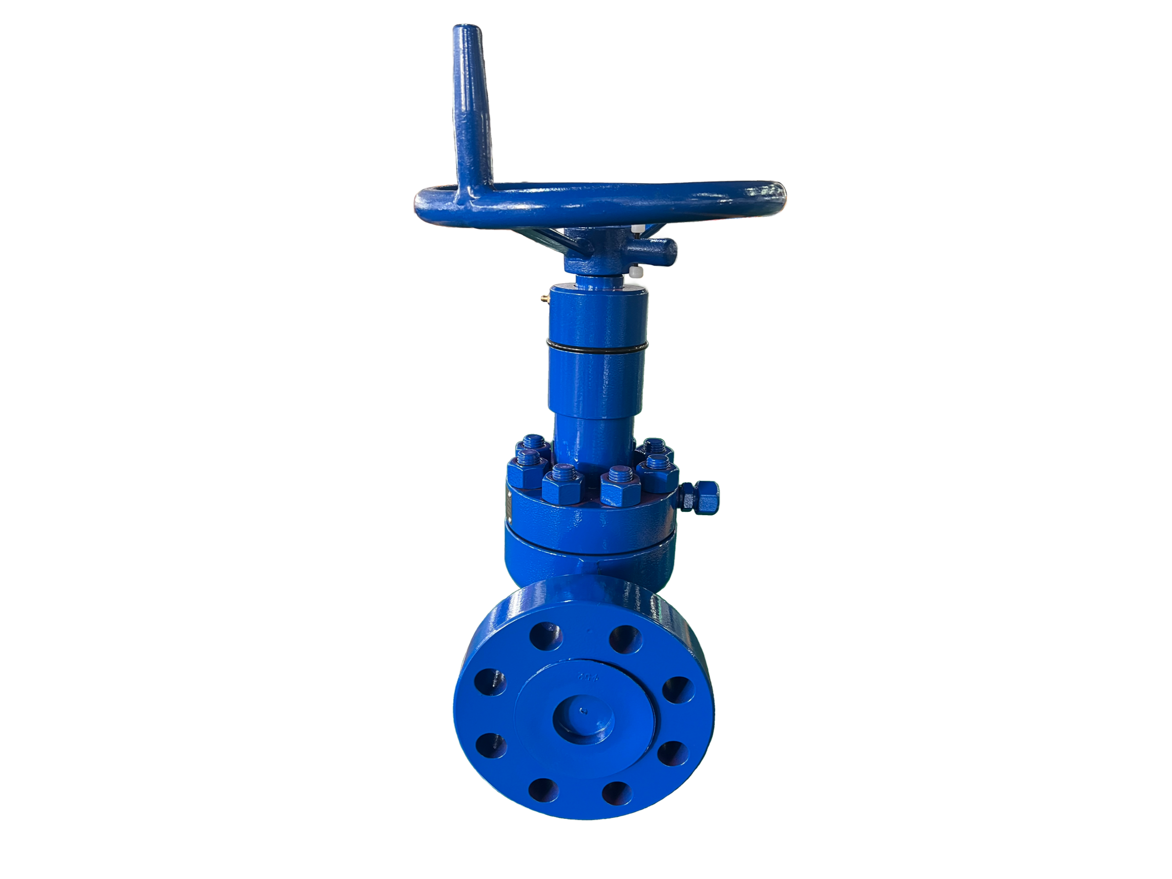
API 6A Gate Valve — 2-1/16″ 5000 psi, Flanged End
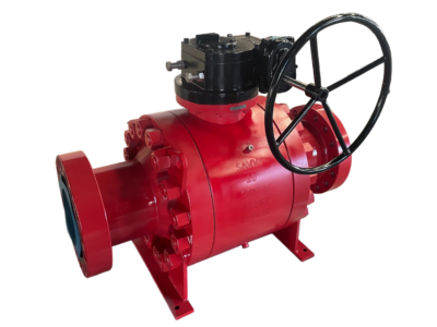
Valve Type: Through-Conduit Gate Valve (Expanding Gate or Slab Gate Design)
Model Example: GV-2116-5K-FL-6A
Nominal Size: 2-1/16″ (52.4 mm bore)
Pressure Rating: 5,000 psi (34.5 MPa)
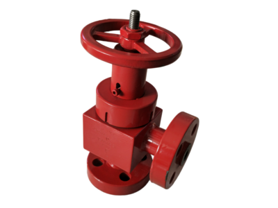
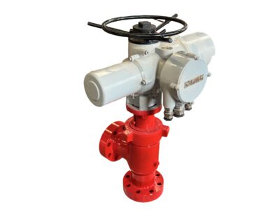
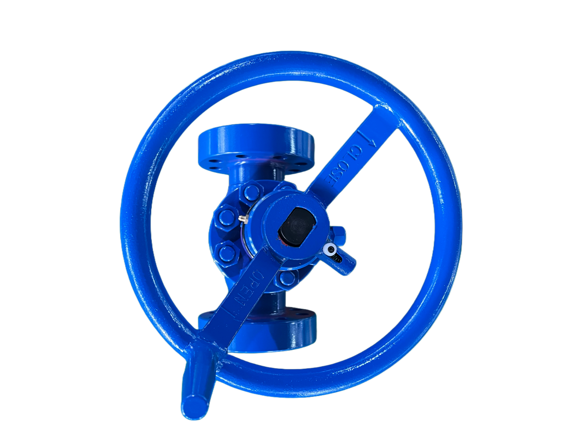
Operation: Handwheel (standard); hydraulic, pneumatic or electric actuation available on request
1. Design Standards & Compliance
Item Standard / Requirement
Design and Manufacture API Specification 6A, 21st Edition
Product Specification Level PSL 1, 2, 3, 3G, 4 (as specified)
Performance Requirement PR 1, PR 2 (qualified to API 6A Annex F)
Material Class AA, BB, CC, DD, EE, FF, HH (per API 6A)
Temperature Rating K, L, P, R, S, T, U, V (−60 °F to +350 °F / −51 °C to +177 °C)
NACE Compliance NACE MR0175 / ISO 15156 (Sour Service), as applicable
Inspection and Testing API 6A / API 598
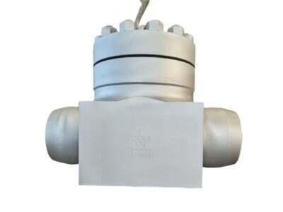
End Connections API 6A Type 6B Flanges with Ring Joint (RTJ)
2. Valve Configuration
Parameter Specification
Nominal Bore 2-1/16″ (52.4 mm)
Working Pressure 5,000 psi (34.5 MPa)
Bore Type Full Bore, Through-Conduit
Gate Design Parallel Expanding Gate (two-piece gate with expansion mechanism) or Slab Gate (through-conduit, floating gate)
Stem Type Non-Rising Stem, supported on two thrust bearings
Seat Design Floating Seats with Metal-to-Metal Sealing; seat arrangement with plastic packing and grease injection ports
Bonnet Type Bolted Bonnet
Bonnet Sealing Soft metallic crush ring or AISI 316 + Graphite gasket
Sealing Principle Metal-to-Metal, Bi-Directional
Flow Direction Bi-directional (preferred sealing side indicated on body)
3. Materials of Construction — Standard Trim Configurations
The table below presents commonly specified material configurations for API 6A gate valves in this size and pressure class. Material class shall be selected based on service conditions (general, sour, corrosive).
Component Material Class AA (General Service, Non-Corrosive) Material Class CC (General Service, Full Stainless, Moderately Corrosive) Material Class EE (Sour Service, Stainless Trim, Moderately Corrosive)
Body API 60K or 75K, AISI 4130 Alloy Steel (forged) API 75K, AISI 410 Stainless Steel API 60K or 75K, AISI 4130 Alloy Steel
Bonnet API 60K or 75K, AISI 4130 Alloy Steel API 75K, ASTM A217 CA-15 Stainless Steel API 60K or 75K, AISI 4130 Alloy Steel
Bonnet Gasket AISI 1018/1020 Low Carbon Steel AISI 304 or 316 Stainless Steel AISI 304 or 316 Stainless Steel
Gate (Disc) API 60K or 75K, AISI 4130, Nitrided AISI 410 Stainless Steel, Nitrided API 60K or 75K, AISI 4130, Nitrided
Stem API 60K or 75K, AISI 4130, Nitrided ASTM A564 630 (17-4PH) Stainless Steel ASTM A564 630 (17-4PH) Stainless Steel
Seat API 60K or 75K, AISI 4130, Nitrided AISI 410 Stainless Steel, Nitrided AISI 410 Stainless Steel, Nitrided
Stem Seal PTFE + NBR / Graphite / PEEK PTFE + FKM / Graphite / PEEK PTFE + FKM / Graphite / PEEK
Studs / Nuts ASTM A193 B7 / A194 2H (or equivalent) ASTM A193 B8M / A194 8M (Stainless) ASTM A193 B7M / A194 2HM (Sour Service)
Additional Material Notes:
For highly corrosive natural gas service with CO₂ content (e.g., 30% CO₂), body and bonnet in ASTM A351 Grade CF8M (316 Stainless Steel) with AISI 316 trim and QPQ surface treatment on gate and segment is a common specification .
For forged body construction, AISI 4130 (75 KSI yield) is widely used for sizes 1-13/16″ to 7-1/16″ across pressure ratings from 2,000 to 20,000 psi .
DD, EE, FF, and HH material classes are designated for sour service per NACE MR0175 .
Gate and seat sealing surfaces are typically nitrided or hardfaced with TCC (Tungsten Carbide Coating) or STL (Stellite) for wear resistance .
4. Dimensions & Weights (5000 psi, Flanged End)
Size Bore (mm) Face-to-Face A (mm) Handwheel Diameter D (mm) Centerline to Bottom B (mm) Centerline to Handwheel Top C (mm) Approx. Weight (kg)
2-1/16″ 52.4 371 330 130 470 75
2-9/16″ 65.1 422 330 150 550 105
3-1/8″ 79.4 473 400 190 555 150
4-1/16″ 103.2 549 480 240 635 280
7-1/16″ 179.4 813 760 355 715 600
*Dimensions per standard API 6A flanged-end gate valves for 5,000 psi working pressure.*
5. Flange Connection Data (2-1/16″ 5000 psi)
Parameter Specification
Flange Type API 6A Type 6B Flange with Ring Joint (RTJ)
Ring Gasket Type R or RX, Size R/Rx 24 (2-1/16″ 5000 psi)
Connection Raised Face Ring Joint (RTJ), complete with companion flanges, ring joint gasket, studs and nuts
Flange Material API 60K SS / 410 SS (compatible with body material)
6. Actuator Mounting (Upon Request)
Mounting Pad: ISO 5211 standard flange integrated on yoke/bracket (sizes as per actuator torque)
Stem Top: Machined with keyway or square per actuator coupling requirements
Actuator Types: Hydraulic fail-safe closed (FSC), double-acting pneumatic, multi-turn electric, hydraulic override; mounting bracket and stem coupling provided
Manual Override: Available (handwheel or hydraulic override)
Accessories: Limit switches, positioners, solenoid valves can be supplied as a package
Balanced Stem Option: Pressure-balancing piston integrally machined on the stem; equalizes pressure forces above and below the piston, reducing operating force and allowing smaller, more cost-effective actuators. Particularly beneficial for high-pressure and deepwater applications
7. Testing & Inspection
Test Item Test Medium Test Pressure Standard
Shell Hydrostatic Test Water 1.5× Rated Working Pressure (7,500 psi / 51.7 MPa) API 6A
Seat Hydrostatic Test Water 1.1× Rated Working Pressure (5,500 psi / 37.9 MPa) API 6A
Seat Pneumatic Test (Optional) Air / Nitrogen Per PSL requirements (typically 15 MPa per PSL 3G) API 6A
Backseat Test Water Per API 6A specifications API 6A
Hold Duration (PSL 3G / 4) — Minimum 15 minutes per test API 6A
Visual & Dimensional — — MSS SP-55, API 6A
All valves are individually tested. Material traceability and test reports available per EN 10204 3.1 or 3.2. PSL 2 or higher provides enhanced QA traceability, including traceable MTRs by heat number; PSL 3G and PSL 4 include additional requirements such as witnessed material tests .
8. Main Features
API 6A Monogrammed — designed, manufactured and tested in accordance with API Specification 6A (21st Edition) .
Full Bore, Through-Conduit Design — effectively eliminates pressure drop and vortex; suitable for pigging and wiping operations .
Parallel Expanding Gate with Inconel springs and angled mating surfaces — provides mechanical expansion for bubble-tight sealing and compensation for thermal expansion and pressure variations .
Metal-to-Metal Sealing with floating seats — ensures bi-directional sealing; seats can be lubricated from grease injection fittings to reduce abrasion and promote long service life.
Non-Rising Stem supported on upper and lower roller thrust bearings — minimizes operation torque and reduces installation space .
Bolted Bonnet construction — allows in-line gate and seat replacement without special tools.
Field-Replaceable Seats — seat replacement possible with valve in line, without need for special tools .
Stem packing can be re-energized with valve under pressure .
Applicable for wellheads, Christmas trees, choke and kill manifolds, production manifolds, and high-pressure isolation in the oil and gas industry .
9. Ordering Information
When ordering, please specify:
Nominal size (2-1/16″) and pressure rating (5,000 psi)
Material Class (AA / BB / CC / DD / EE / FF / HH) based on service conditions
Product Specification Level (PSL) : PSL 1, 2, 3, 3G, or 4
Performance Requirement (PR) : PR 1 or PR 2
Temperature Class (K, L, P, R, S, T, U, V)
NACE MR0175 compliance required (Yes/No)
Gate Design : Expanding Gate or Slab Gate
Stem Type : Balanced Stem or Standard Non-Rising Stem
Manual or actuated operation, and if actuated, the actuator type, power supply / air pressure, control signal
Any special coatings or surface treatments (e.g., QPQ, nitriding, TCC/STL hardfacing)
Desired documentation level (3.1 / 3.2 certificates, PMI, NDE, Charpy impact test results as required)