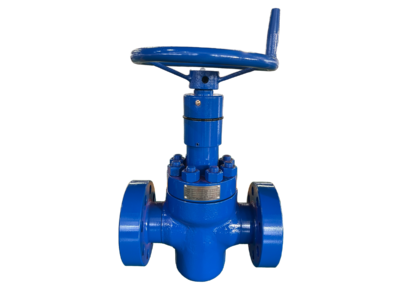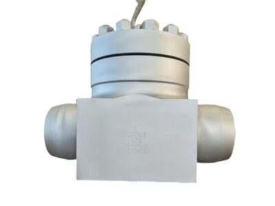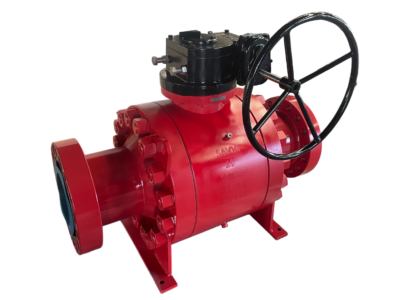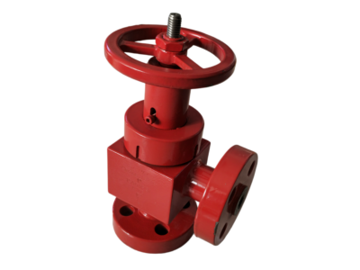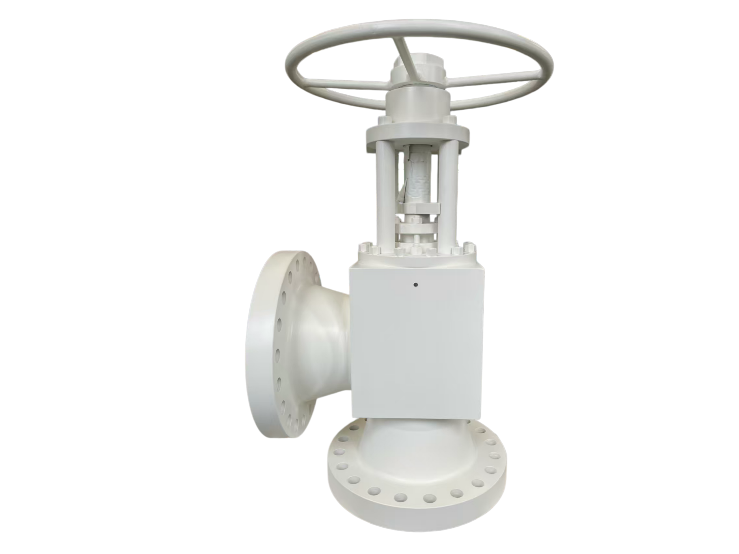
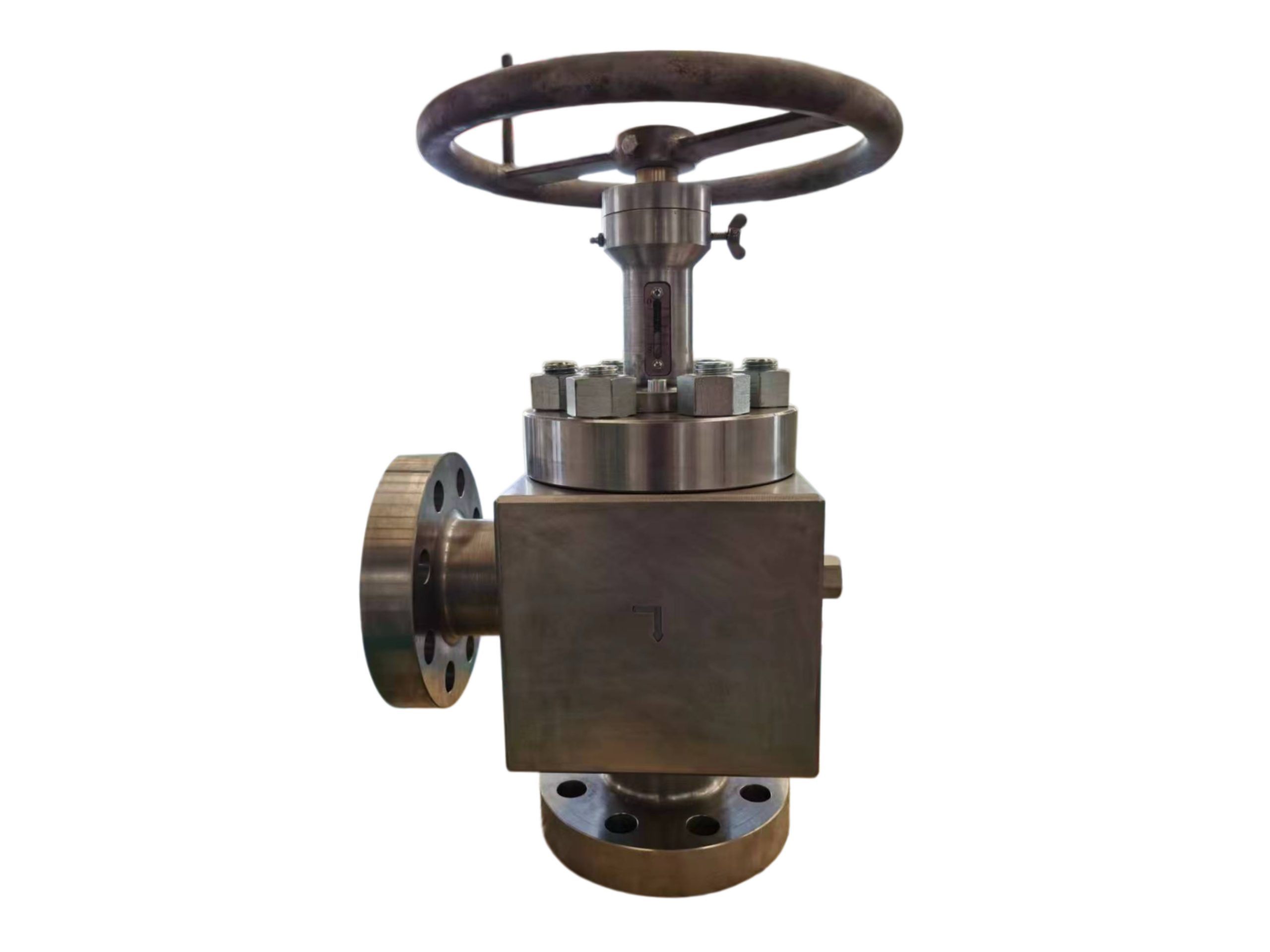

Choke Valve Adjustable Die Forged—12″*10″ 600LB RF
Description
Technical Data Sheet – Open Die Forged Adjustable Choke Valve
Size: 12″ × 10″ (Reducing) | Pressure Class: 600 LB | End Connection: Raised Face (RF) Flanged
Body Manufacturing Process: Open Die Forging (Free Forging)
1. General Description
The 12″ × 10″ – 600LB Open Die Forged Adjustable Choke Valve is a high‑performance flow control device designed for precise regulation of fluid pressure and flow rate in oil & gas wellhead assemblies, choke manifolds, and high‑pressure pipeline systems.
The reducing design features a 12″ inlet flange with internal seat bore reduced to 10″, providing controlled flow restriction and pressure drop across the throttling orifice. The open die forging process for the valve body ensures superior metallurgical integrity, grain flow continuity, and mechanical strength compared to cast or bar‑stock alternatives. The needle‑type trim is hardfaced with Stellite 6 for exceptional erosion and cavitation resistance.
Typical applications include wellhead flow control, production manifold throttling, injection well regulation, and pressure let‑down stations in upstream oil & gas operations.
2. Design Features
Feature Description
Body Construction Globe pattern or Angle pattern (as specified)
Manufacturing Process Open die forging (free forging) – from ingot or large billet
End Connections RF flanges per ASME B16.5 Class 600 (12″ inlet / 12″ outlet)
Port Reduction Inlet: NPS 12, internal seat bore reduced to approx. NPS 10
Trim Type Needle / plug‑type choke valve trim
Bonnet Design Bolted bonnet with forged construction
Stem Design A182 F6a (13Cr) stainless steel, anti‑galling
Operation Handwheel (standard) / Gearbox / Actuator‑ready
Flow Direction Flow over seat (preferred) or flow under seat
Hardfacing Stellite 6 or equivalent on seat and plug contact surfaces
Renewable Seat Integral or renewable seat ring design
3. Applicable Standards
Parameter Standard
Design & Manufacture API 6A (Specification for Wellhead and Christmas Tree Equipment)
Pressure‑Temperature Rating ASME B16.34
Flange Dimensions ASME B16.5 Class 600 RF
Face‑to‑Face Dimension Per API 6D / ASME B16.10 or manufacturer standard
Valve Inspection & Testing API 598 / ISO 5208
Forgings ASTM A105 / ASME SA‑105 (Open die forgings, normalized)
Non‑destructive Examination (NDE) Ultrasonic testing per ASTM A388 (body forging)
Sour Service (optional) NACE MR0175 / ISO 15156
Fire Safety (optional) API 6FA / API 607
Fugitive Emissions (optional) ISO 15848
4. Material Specification (Standard Carbon Steel Option)
Component Material Standard / Remarks
Body ASTM A105 Open die forged, normalized
Bonnet / Cover ASTM A105 Forged, bolted bonnet design
Disc / Plug / Needle ASTM A105 + Hardfacing Stellite 6 or 13Cr – erosion resistant
Seat Ring ASTM A105 + Hardfacing Integral or renewable, hardfaced sealing surface
Stem ASTM A182 F6a (13Cr) Stainless steel, anti‑galling
Packing Flexible Graphite With Inconel wire reinforcement
Gasket Spiral Wound 304SS + Graphite
Stud Bolts ASTM A193 B7 High strength alloy steel
Nuts ASTM A194 2H Carbon steel
*For corrosive or sour service (H₂S / CO₂ environments), specify body and trim materials per NACE MR0175 with appropriate Material Class (AA, BB, CC, DD, EE, FF, HH). Tungsten carbide trim optional for high‑ΔP abrasive services.*
5. Pressure‑Temperature Ratings (A105 Body – Class 600, ASME B16.34)
Temperature Max Working Pressure
-20 to 100°F (-29 to 38°C) 1480 psig (102 bar)
200°F (93°C) 1350 psig (93 bar)
300°F (149°C) 1235 psig (85 bar)
400°F (204°C) 1130 psig (78 bar)
500°F (260°C) 1015 psig (70 bar)
600°F (316°C) 975 psig (67.2 bar)
700°F (371°C) 950 psig (65.5 bar)
800°F (427°C) 915 psig (63.1 bar)
*Design Temperature Range: -29°C to +425°C (-20°F to +800°F) for standard A105 construction.*
6. Dimensions & Connections
Parameter Value
Inlet Flange 12″ Class 600 RF per ASME B16.5
Outlet Flange 12″ Class 600 RF per ASME B16.5
Reducing Bore Inlet NPS 12, seat bore reduced to ~NPS 10
Face‑to‑Face Length (L) Per API 6D / ASME B16.10 or manufacturer standard
Flange O.D. (12″ Class 600 RF) 527 mm (20.75 in)
Bolt Circle Diameter 483 mm (19.0 in)
Number of Bolt Holes 16
Bolt Hole Diameter 35 mm (1.38 in)
Height (approx., handwheel) Contact manufacturer for final GA drawing
Approx. Weight Contact manufacturer for final value
Dimensions and weight are manufacturer‑specific for open‑die forged designs. Contact for certified GA drawings.
7. Flow Characteristics
Parameter Specification
Flow Characteristic Linear or Equal Percentage (as specified)
Seat Leakage Rate Class IV or Class V per FCI 70‑2 / IEC 60534
Cv (Flow Coefficient, max) Determined by seat bore and trim design – contact manufacturer
Cv Rangeability Typically 30:1 to 50:1 depending on trim
Due to the custom nature of open‑die forging, exact Cv values are application‑specific. Please provide process conditions (flow rate, ΔP, fluid properties) for sizing.
8. Open Die Forging Advantage
Property Open Die Forging Casting Bar Stock Machining
Grain flow Continuous, directional Random, non‑directional Cut across original bar grain
Mechanical strength Superior impact & fatigue resistance Lower Moderate
Porosity / voids None Potential shrinkage/porosity Minimal (depends on bar origin)
Weld repair Not permitted (by API 6A) Restricted Not permitted
Ultrasonic inspection Applicable Less reliable Applicable
Suitability for high pressure Excellent Good (with NDE) Moderate
Open die forging ensures maximum structural integrity, making this valve ideal for high‑pressure, high‑temperature, and critical choke applications.
9. Trim Hardfacing & Wear Resistance
Parameter Specification
Hardfacing Material Stellite 6 or equivalent
Hardfacing Location Seat contact surface and disc/plug contact surface
Minimum Hardness (after welding) 350–450 HB
Erosion & Cavitation Resistance Hardfacing ensures long service life under multi‑phase flow with sand/solids
Alternate Trim Materials Tungsten carbide, Inconel 625, or 17‑4PH (upon request)
10. Non‑destructive Examination (NDE)
Component Examination Method Standard
Body forging Ultrasonic testing (100%) ASTM A388
Bonnet forging Ultrasonic testing ASTM A388
Seat area Liquid penetrant examination (LPE) ASTM E165 / E1417
Stem Liquid penetrant examination ASTM E165 / E1417
Critical areas (seat, bore, welds) Additional NDE per API 6A PSL requirements Per API 6A
11. Testing per API 598 / API 6A
Test Pressure Duration Acceptance
Shell Hydrostatic 1.5 × rating (2220 psig) As per standard No visible leakage
High‑Pressure Seat 1.1 × rating (1628 psig) As per standard Leakage per Class IV / V
Low‑Pressure Air Seat 90 psig (0.6 MPa) As per standard Leakage per Class IV / V
For API 6A Product Specification Levels (PSL 1, 2, 3, 4), testing and documentation requirements vary. Specify required PSL at time of order.
12. Marking (per MSS SP‑25 / API 6A)
Manufacturer’s name / logo
12″ × 10″ – 600 LB
Body material: A105
API 6A
Heat number
Temperature class (per API 6A)
Material class (if applicable)
Flow direction arrow
13. Ordering Information
To order a 12″ × 10″ – 600LB Open Die Forged Adjustable Choke Valve, please specify:
Valve size: 12″ × 10″ (reducing) – 12″ flanged ends, 10″ seat bore
Pressure class: 600 LB
Body material: ASTM A105 (or low‑temp / stainless / duplex)
Body style: Globe pattern (standard) or Angle pattern
End connection: RF flanges per ASME B16.5 Class 600 (RTJ available upon request)
Trim material: A105 + Stellite 6 hardfacing (Tungsten carbide optional)
Operation: Handwheel (standard) / Gearbox / Pneumatic actuator / Electric actuator
Seat leakage rate: Class IV (standard) or Class V
NACE MR0175 / ISO 15156 (sour service): Yes / No
Fire‑safe certification: Yes / No (API 6FA)
Product Specification Level (PSL): PSL 1, 2, 3, or 4
Flow characteristic: Linear (standard) or Equal percentage
14. Important Notes
Open die forging is a mandatory requirement – machining from bar stock or casting is NOT acceptable per API 6A for pressure‑containing components in this construction class.
The reducing port design (12″ inlet × 10″ seat bore) provides controlled flow throttling while maintaining full‑size flange compatibility on both ends.
Stellite 6 hardfacing on seat and plug contact surfaces ensures long‑term erosion resistance, especially in sand‑laden multi‑phase flow environments.
No welding repair is permitted on forged pressure‑containing components per API 6A requirements for PSL 3 and above.
For hydraulic or pneumatic actuator mounting, the valve shall be supplied with an ISO 5211 mounting pad and stem extension as required.
For angle pattern body design – preferred for high pressure drop applications where fluid directional change improves cavitation resistance and reduces erosion on downstream piping.
Disclaimer: This data sheet provides typical values for a 12″ × 10″ Class 600 open die forged adjustable choke valve. Actual dimensions, weight, Cv values, and exact material certifications depend on the specific manufacturer and product specification level (PSL). Refer to certified manufacturing drawings, material test reports (MTRs), and GA drawings for final specifications.
Issued by: [Your Company Name]
Revision: 1.0 / Date: [Current Date]