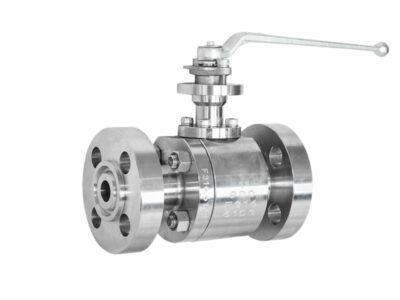
2-Piece Cryogenic Floating Ball Valves—6″ 300LB RF
Description
Technical Data Sheet
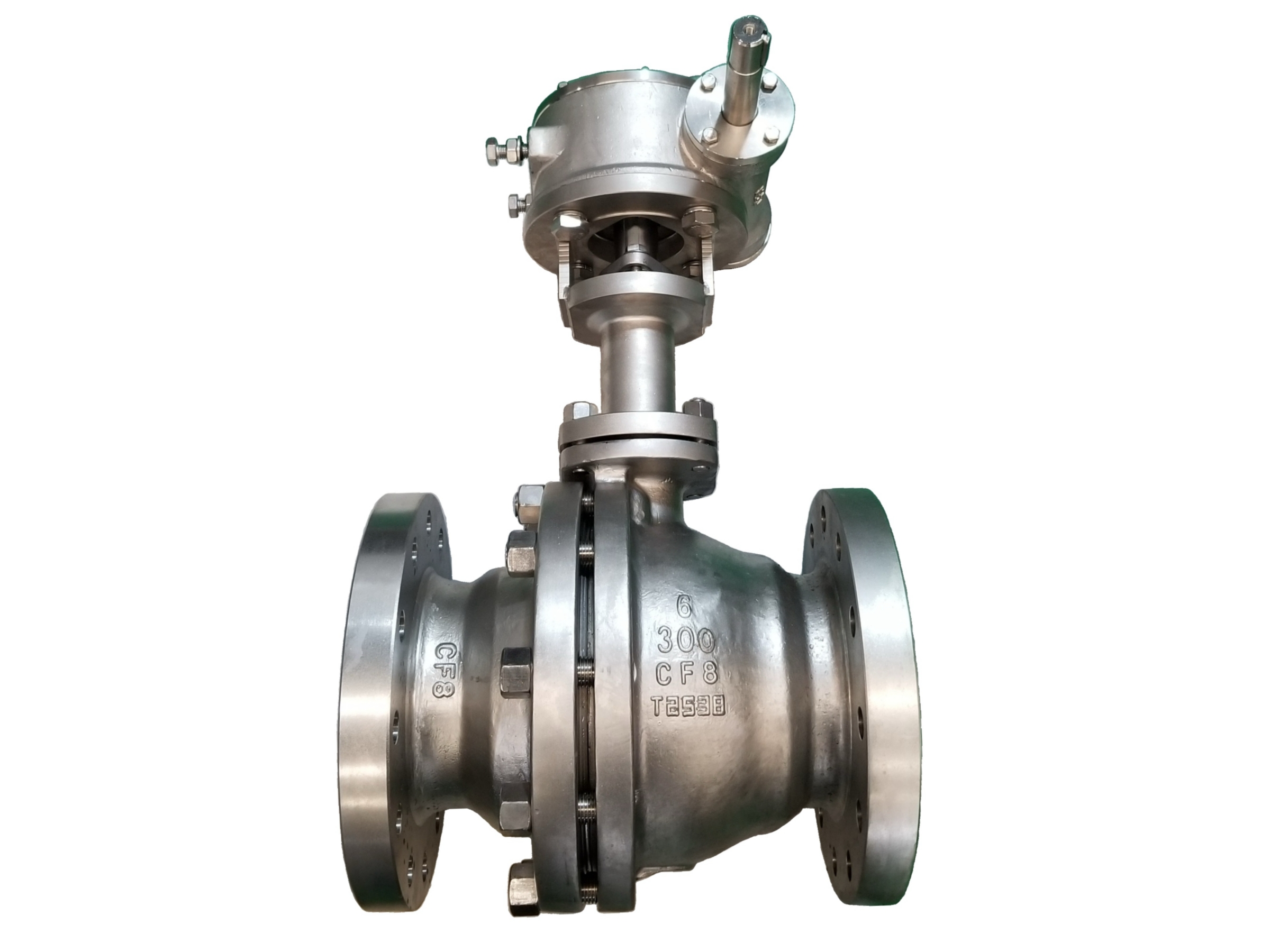
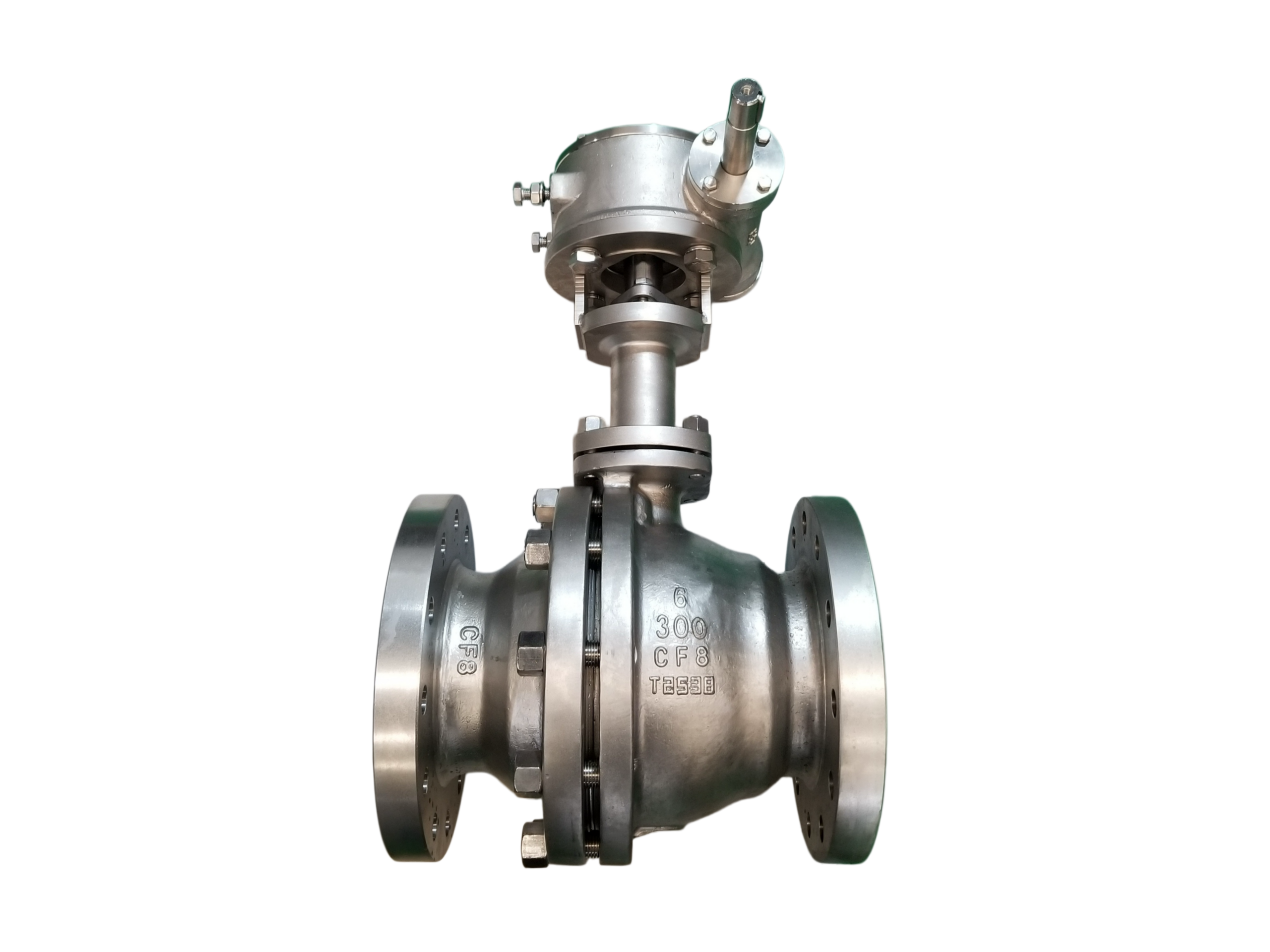
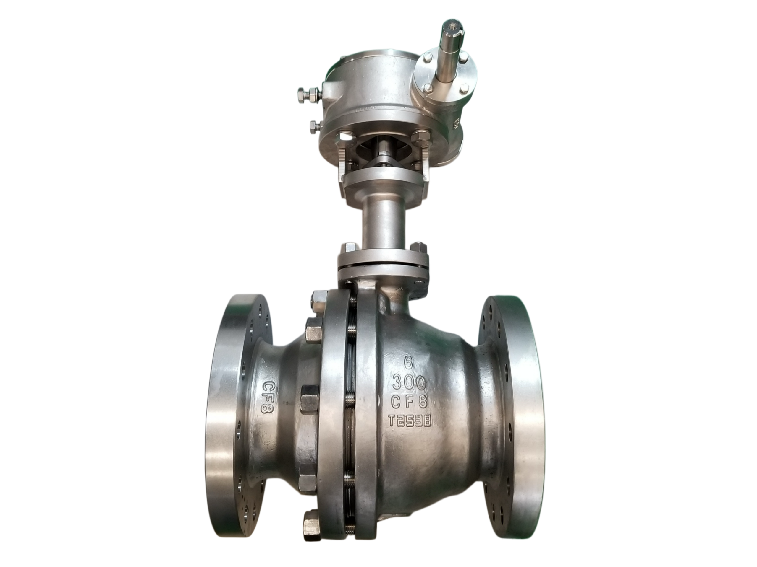
2-Piece Cryogenic Floating Ball Valve – Gear Operated
Size: 6″ (DN150)
Pressure Class: 300LB
End Connection: Raised Face (RF) Flanged
Body Material: ASTM A351 CF8
1. General Description
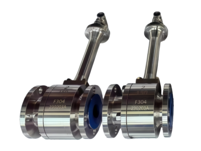
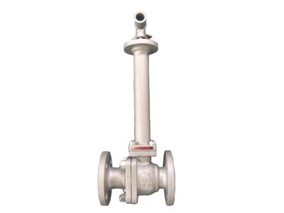
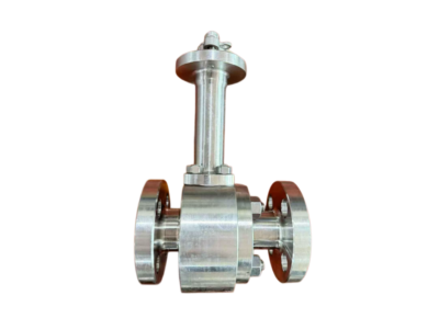
This two-piece, side-entry cryogenic floating ball valve is designed for isolation and on-off service of liquefied gases such as LNG, liquid nitrogen, liquid oxygen, and other cryogenic fluids down to -196 °C (-320 °F). The body and extended bonnet are precision cast from ASTM A351 CF8 stainless steel. The valve is operated via a manual gear operator with a handwheel, providing mechanical advantage for low-torque operation on this large-bore valve. The gearbox is supplied with an ISO 5211 top mounting pad as standard, allowing straightforward upgrade to a pneumatic or electric actuator if required in the future. All cryogenic design features, including blow-out proof stem, antistatic device, and self-relieving seats, are incorporated to ensure safe and reliable performance.
2. Design Codes & Standards
Item Applicable Standard
Basic Design & Manufacture API 608, API 6D, BS 6364, ISO 17292
Pressure-Temperature Rating ASME B16.34
Flanged Ends ASME B16.5 (RF)
Face-to-Face Dimensions ASME B16.10 (Long Pattern)
Inspection & Testing API 598, BS 6364 (Cryogenic Test)
Fire-Safe Design (Optional) API 607 / ISO 10497
Casting Material ASTM A351 CF8
Gear Operator Interface ISO 5211 (standard pad)
3. Main Technical Specifications
Nominal Size: 6″ (DN150)
Pressure Class: Class 300
Bore Type: Full Bore (standard) / Reduced Bore (optional)
Connection: Flanged RF per ASME B16.5
Body / Bonnet Material: ASTM A351 CF8
Ball Material: CF8 / SS304 (SS316 with hard chrome plating optional)
Seat Material: PCTFE (Standard) / TFM / Metal (Optional)
Stem Material: ASTM A182 F304 / F316 or 17-4PH
Packing: Flexible Graphite + PTFE braided
Body-Bonnet Gasket: 304+Graphite Spiral Wound or PTFE
Design Temperature Range: -196 °C to +200 °C (-320 °F to +392 °F)
Leakage Class: Zero Leakage (API 598)
Operation: Manual gear operator with handwheel; ISO 5211 mounting pad for optional actuator
Design Features:
Extended bonnet with integral drip plate (keeps packing area above 0 °C)
Blow-out proof stem
Antistatic device (ball-stem-body electrical continuity)
Self-relieving seats (cavity overpressure vents to upstream side)
Lockable handwheel (optional)
4. Materials of Major Parts
No. Part Name Material Standard
1 Body ASTM A351 CF8 ASTM A351
2 Bonnet (Extended) ASTM A351 CF8 ASTM A351
3 Ball CF8 / A182 F304 ASTM A351 / A182
4 Seat Ring PCTFE —
5 Stem A182 F304 / A564 17-4PH ASTM A182 / A564
6 Packing Graphite + PTFE braided —
7 Body-Bonnet Gasket 304+Graphite Spiral Wound ASME B16.20
8 Stud A193 B8 (Class 1) ASTM A193
9 Nut A194 8 ASTM A194
10 Drip Plate SS304 —
11 Antistatic Spring SS316 —
12 Gear Operator Ductile iron / Carbon steel, epoxy painted, with ISO 5211 top flange —
13 Handwheel Carbon steel (painted) / SS304 —
5. Principal Dimensions (6″ 300LB RF)
Symbol Description Value (mm) Value (inch)
L Face-to-Face Length 403 15.87″
D Flange Outer Diameter 318 12.50″
D1 Bolt Circle Diameter 270 10.63″
D2 Bolt Hole Diameter 22.2 0.88″
b Flange Thickness (excl. RF) 25.4 1.00″
H Centerline to Top of ISO Pad (approx.) ~700 ~27.56″
H1 Centerline to Handwheel Centre (approx.) ~550 ~21.65″
ISO Pad Standard mounting flange size F10 / F12 —
Cv Rated Flow Coefficient (Full Bore) ~1200 —
MAST Max. Allowable Stem Torque 800 N·m —
Weight Approx. Weight (incl. gearbox) ~160 kg —
Bolt Holes Quantity & Size 12 × 7/8″ UNC —
Note: All dimensions comply with ASME B16.10 and B16.5. Height values are approximate and will be confirmed on the certified dimensional drawing prior to order.
6. Performance Tests & Inspection
Shell Test: 1.5 × Class 300 rated pressure (≈ 77.6 bar / 1125 psi), duration ≥1 minute, no leakage or permanent deformation.
High-Pressure Seat Test: 1.1 × rated pressure (≈ 56.9 bar), water, zero leakage.
Low-Pressure Seat Test: 0.6 bar pneumatic, zero leakage.
Cryogenic Test (BS 6364): Valve submerged in liquid nitrogen at -196 °C. Cycle test and seat leakage test performed; packing zone must show no leakage and remain functional. Operation torque measured at cryogenic temperature.
Visual & Dimensional Inspection: 100% casting examination free from porosity and cracks. Flange sealing face finish Ra 3.2–6.3 μm. Face-to-face, flange, and gear interface dimensions verified.
Material Certification: EN 10204 Type 3.1 certification available. PMI (Positive Material Identification) optional.
7. Installation & Maintenance Tips
Orientation: The extended bonnet must be installed with the stem vertical (max. deviation ±15°). This is essential to maintain the gas column that isolates the packing from cryogenic temperatures.
Gear Operator: The gearbox is factory-lubricated and adjusted. The handwheel rotates clockwise to close. Do not exceed the specified rim pull force to avoid over-torquing the stem.
Actuator Mounting (if applicable): The ISO 5211 pad allows direct mounting of a pneumatic or electric actuator. Ensure proper alignment and torque settings.
Startup in Cryogenic Service: After the first cool-down cycle, re-tighten body-bonnet bolts and the packing gland uniformly to compensate for thermal contraction.
Oxygen Service: For LOX or gaseous oxygen applications, the valve must be specially degreased and handled in a clean environment. Hydrocarbon-based lubricants are strictly prohibited.
Maintenance: Periodically cycle the valve fully open and closed to prevent build-up. Check gearbox lubrication and packing condition at regular intervals.
This technical data sheet is intended for product selection and general reference. The manufacturer reserves the right to modify designs and materials without prior notice. All final specifications are subject to the approved order-specific documentation and drawings.