2-Piece Cryogenic Floating Ball Valves Open Die Forged
Description
Technical Data Sheet
2-Piece Cryogenic Floating Ball Valves
Forging Process: Open Die Forged
Design: Side Entry, Full/Reduced Bore, Extended Bonnet
1. General Description
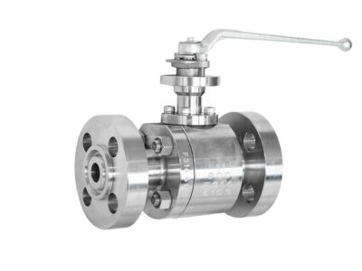
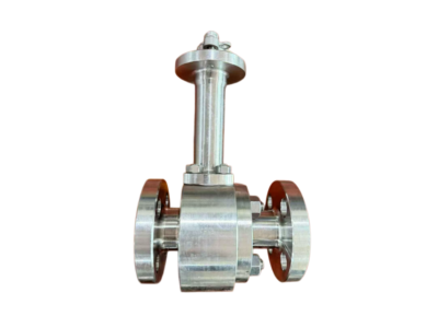
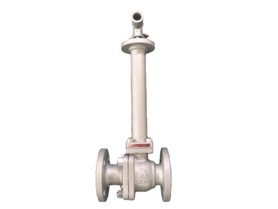
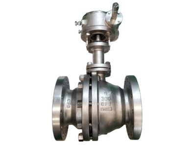
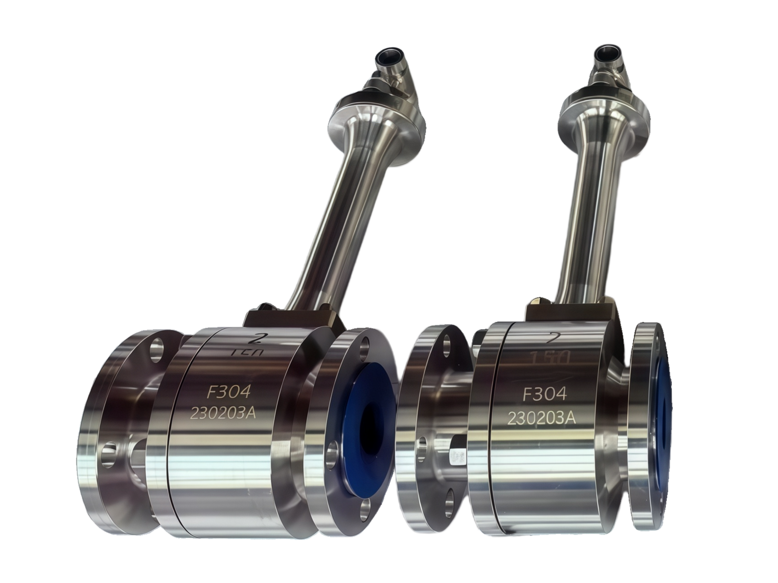
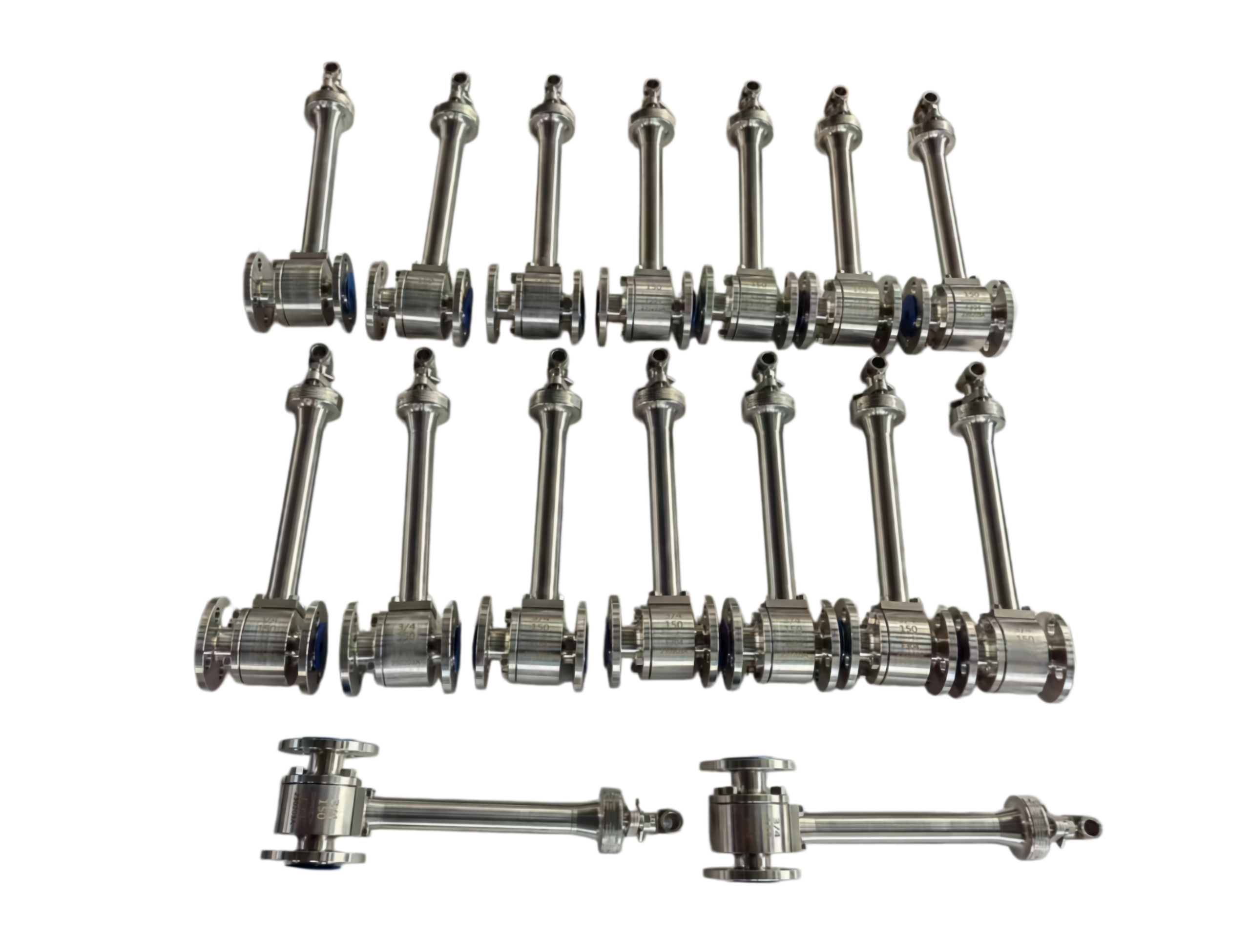
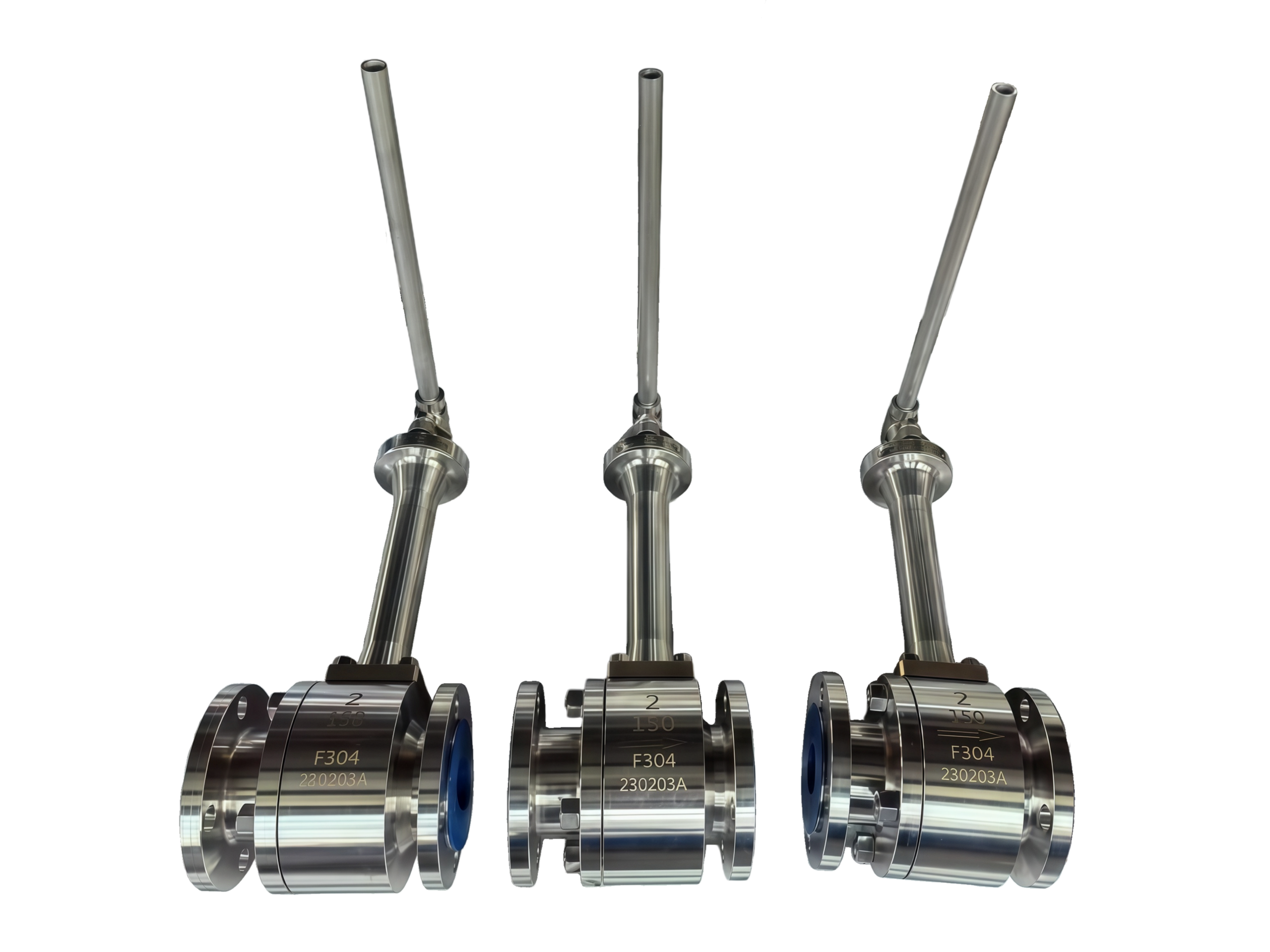
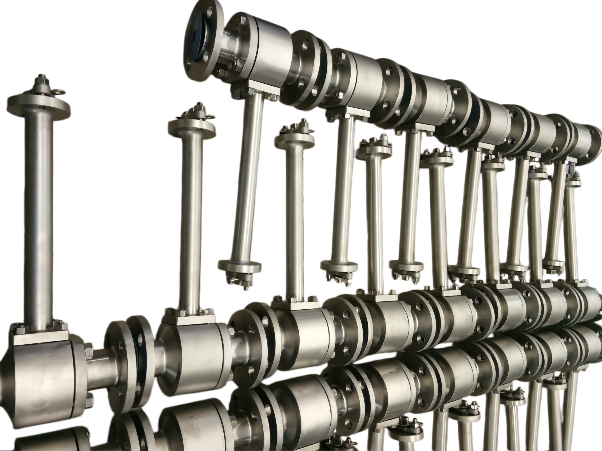
This series of two-piece, side-entry cryogenic floating ball valves is manufactured using open die forged bodies and bonnets. The open die forging process ensures superior structural integrity, grain flow, and mechanical properties essential for reliable service at cryogenic temperatures. The extended bonnet with integral drip plate effectively isolates the stuffing box from the cold media, maintaining a packing area temperature above 0 °C and preventing ice formation. These valves are designed for on-off and isolation service of liquefied gases such as LNG, LIN, LOX, liquid argon, and other cryogenic fluids, offering bubble-tight shutoff, low operating torque, and long service life. Standard end connections are flanged RF, with butt-weld ends available upon request.
2. Design Codes & Standards
Item Applicable Standard
Basic Design & Manufacture API 608, API 6D, BS 6364, ISO 17292
Pressure-Temperature Rating ASME B16.34
Flanged Ends ASME B16.5 (RF) / ASME B16.47 (if applicable)
Butt-Weld Ends ASME B16.25
Face-to-Face / End-to-End Dimensions ASME B16.10 (Long Pattern)
Inspection & Testing API 598, BS 6364 (Cryogenic Test)
Fire-Safe (Optional) API 607 / ISO 10497
Forging Standard ASTM A182, A350, A105 (depending on material)
3. Technical Specifications
Size Range: 1/2″ to 12″ (DN15 – DN300), larger sizes on request
Pressure Class: Class 150, 300, 600, 900 (150LB, 300LB, 600LB, 900LB)
Bore Type: Full Bore (standard), Reduced Bore available
Design Temperature: -196 °C to +200 °C (-320 °F to +392 °F)
Leakage Class: Zero leakage (API 598)
End Connections: Flanged Raised Face (RF), Butt-Weld (BW), or combination
Operation: Lever (up to 2″/DN50), Gearbox (≥ 3″/DN80), Pneumatic/Electric actuator ready with ISO 5211 top flange
Seat Material: PCTFE (standard), TFM, PEEK, Metal (optional)
Body & Bonnet Material (Open Die Forged): ASTM A182 F316/F316L, F304/F304L, A350 LF2, A105N, and other alloys upon request
Ball & Stem Material: SS316/316L, F51 (Duplex), 17-4PH, or A182 F316
Packing: Flexible Graphite / PTFE or Graphite + PTFE braided
Design Features:
Blow-out proof stem
Antistatic device (spring-loaded contact ensuring conductivity between ball, stem and body)
Self-relieving seats (cavity pressure automatically vents to the upstream side)
Fire-safe design certification available
Cavity vent/drain connections optional
4. Materials of Major Parts (Typical, for F316/F316L construction)
Part No. Part Name Material Standard
1 Body A182 F316/F316L (Open Die Forged) ASTM A182
2 Bonnet (Extended) A182 F316/F316L (Open Die Forged) ASTM A182
3 Ball A182 F316 / A479 316L ASTM A182 / A479
4 Seat Ring PCTFE / TFM —
5 Stem A182 F316 / A564 17-4PH ASTM A182 / A564
6 Packing Graphite / PTFE —
7 Body-Bonnet Gasket Spiral Wound 316L + Graphite ASME B16.20
8 Stud A193 B8M (Class 1) ASTM A193
9 Nut A194 8M ASTM A194
10 Drip Plate SS304/316L —
11 Antistatic Spring SS316 —
12 Handle / Gearbox Carbon Steel / SS304 —
*For LF2 or other material classes, bolting and trim materials are adjusted accordingly (e.g., A193 B7 / A194 2H for low-temp carbon steel).*
5. Performance Testing & Quality Assurance
Shell Test: 1.5 × Rated Pressure (water), hold time per API 598, no visible leakage.
Seat Test (High Pressure): 1.1 × Rated Pressure (water), zero leakage.
Seat Test (Low Pressure): 0.6 bar (6 barg) pneumatic, zero leakage.
Cryogenic Test (BS 6364): Valve fully immersed in liquid nitrogen (-196 °C) and subjected to operational torque measurement and seat leakage tests; packing area must remain functional without external leakage.
Additional Tests: PMI (Positive Material Identification), NDE (Liquid Penetrant for forgings), and dimensional verification. EN 10204 Type 3.1 certification available.
6. Installation & Maintenance Notes
Orientation: The extended bonnet must be installed with the stem vertical, within ±15° deviation, to ensure the cold column correctly isolates the packing and actuator.
Flow Direction: Bidirectional flow is permissible; typical installation is with the cavity pressure relieving to the upstream.
Piping Stress: Flanged or welded ends should be connected without imposing excessive piping loads. For buttweld ends, protect the ball and seats during welding.
Initial Cool-down: After the first cryogenic cycle, retighten the body-bonnet bolting and the packing gland bolts to compensate for contraction.
Oxygen Service: Valves intended for LOX or gaseous oxygen must be specially cleaned, degreased, and assembled in a clean environment. Do not use hydrocarbon lubricants.
This product technical data sheet represents our standard range and is subject to continuous improvement. For specific project requirements, individual data sheets with detailed dimensions, Cv values, and material certificates can be provided upon request. Manufacturers reserve the right to modify designs without prior notice. Final confirmed dimensions and specifications are subject to the order-specific approved drawing.