2-Piece Cryogenic Floating Ball Valve Open Die Forged—1/2″ 300LB RF
Description
Technical Data Sheet
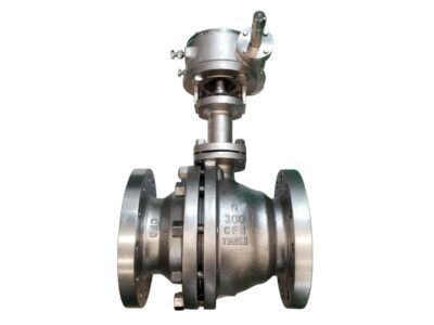
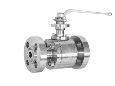
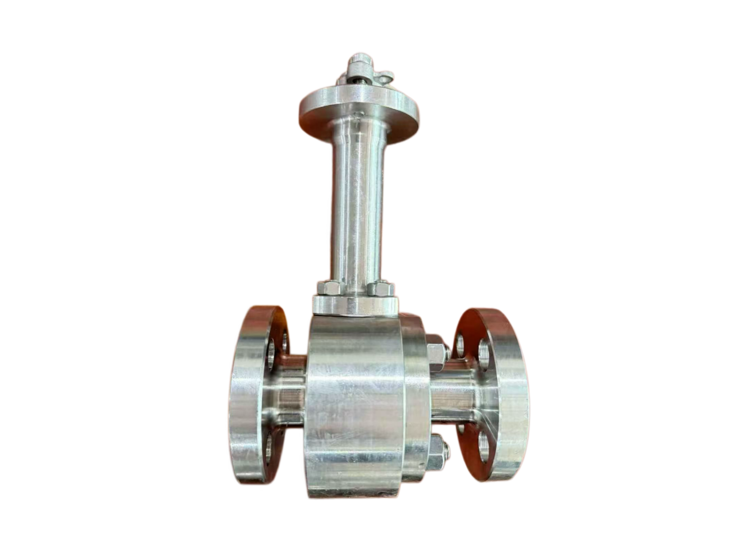
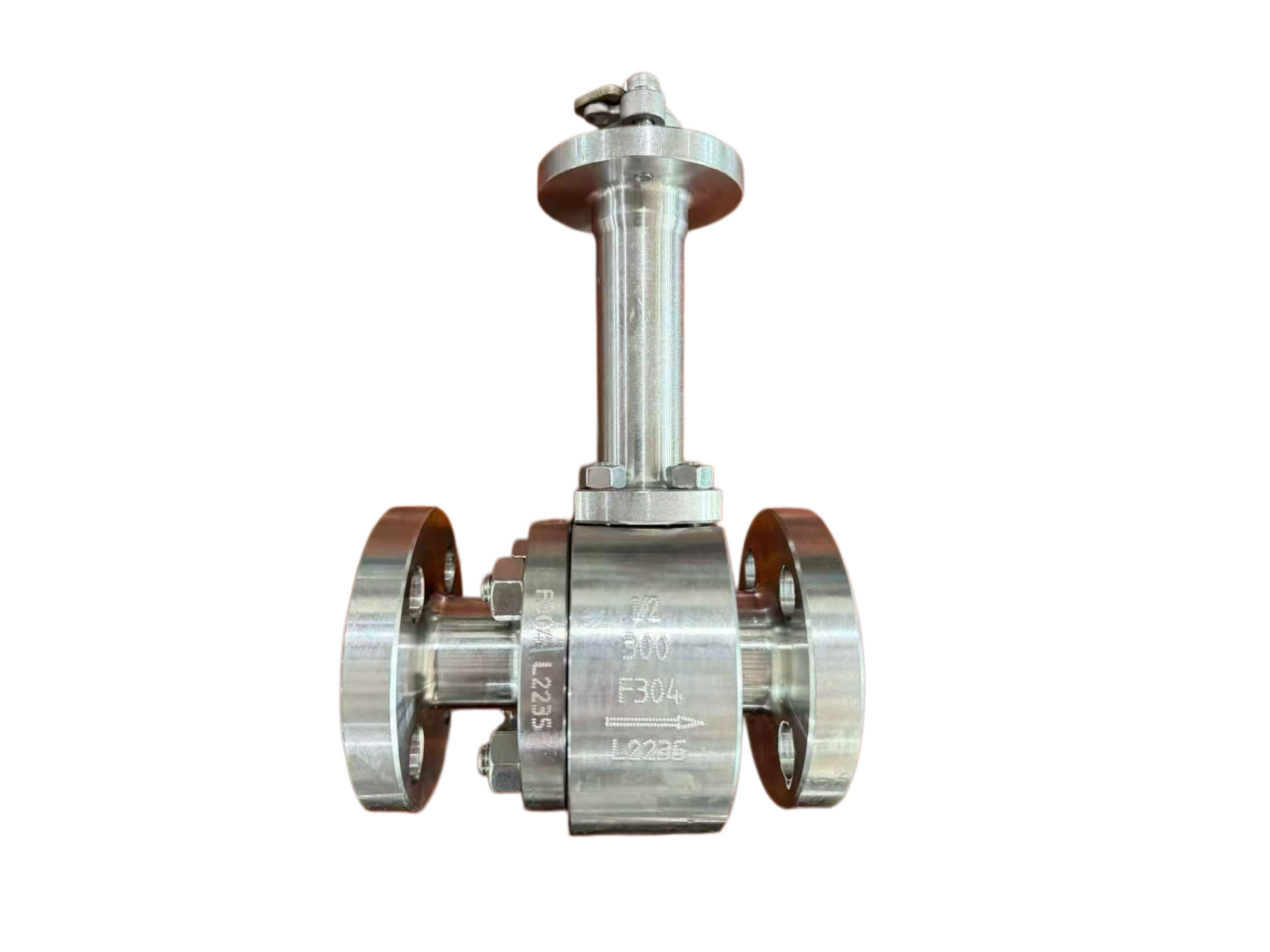
2-Piece Cryogenic Floating Ball Valve, Open Die Forged
Size & Class: 1/2″ 300LB RF
Body Material: ASTM A182 F316 (Standard) / LF2, F304 available on request
1. General Description
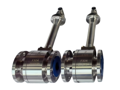
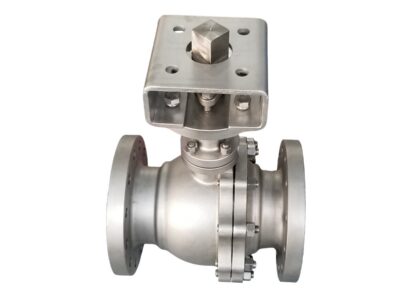
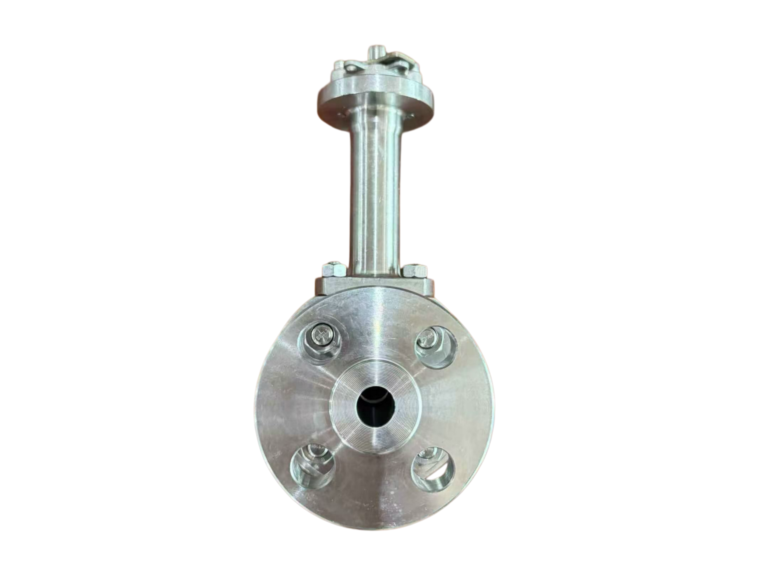
This is a two-piece, side-entry, cryogenic floating ball valve. The body and bonnet are manufactured by the open die forging process from ASTM A182 F316 stainless steel, providing excellent low-temperature toughness and corrosion resistance. The extended bonnet design incorporates a drip plate, ensuring the stuffing box area remains above freezing temperature during cryogenic service to prevent icing. The valve features a blow-out proof stem, antistatic device, and self-relieving cavity pressure function. It is suitable for cryogenic media such as LNG, liquid nitrogen (LIN), liquid oxygen (LOX), etc., with a minimum operating temperature of -196 °C. Flanged ends comply with ASME B16.5 Raised Face (RF), Class 300.
2. Design Codes & Standards
Item Applicable Standard
Design & Manufacture API 608, API 6D, BS 6364, ISO 17292
Pressure-Temperature Rating ASME B16.34
End Connections ASME B16.5 (RF)
Face-to-Face Dimensions ASME B16.10 (Long Pattern)
Inspection & Testing API 598, BS 6364 (Cryogenic Test)
Fire-Safe Design API 607 / ISO 10497 (Optional)
Forging Standard ASTM A182 (F316)
3. Main Technical Specifications
Nominal Size: 1/2″ (DN15)
Pressure Class: Class 300 (300LB)
Connection Type: Flanged RF
Body/Bonnet Material: ASTM A182 F316 (Open Die Forged)
Ball Material: SS316 or A182 F316
Seat Material: PCTFE (Standard) / Metal (Optional)
Stem Material: A182 F316 / 17-4PH
Packing: Flexible Graphite + PTFE braided
Gasket: 304+Graphite Spiral Wound / PTFE
Operation: Lever handle (with ISO 5211 mounting pad, actuator ready)
Temperature Range: -196 °C to +200 °C
Leakage Class: Zero leakage (per API 598)
Design Features:
Extended bonnet with drip plate for thermal isolation
Blow-out proof stem design
Antistatic device (electrical continuity between ball, stem and body)
Self-relieving seats (cavity pressure automatically relieves upstream)
Full bore (standard) / Reduced bore (optional)
4. Materials of Major Parts
No. Part Name Material Standard
1 Body A182 F316 ASTM A182
2 Bonnet A182 F316 ASTM A182
3 Ball SS316 / A182 F316 ASTM A276 / A182
4 Seat PCTFE —
5 Stem A182 F316 / 17-4PH ASTM A182 / A564
6 Packing Flexible Graphite + PTFE braided —
7 Gasket 304+Graphite Spiral Wound / PTFE —
8 Stud A193 B8 (Class 1) ASTM A193
9 Nut A194 8 ASTM A194
10 Lever Handle SS304 —
11 Drip Plate SS304 —
12 Antistatic Spring SS316 —
5. Principal Dimensions (1/2″ 300LB RF)
Symbol Description Value (mm) Value (inch)
L Face-to-Face Length 165 6.50″
D Flange Outer Diameter 95 3.74″
D1 Bolt Circle Diameter 66.7 2.63″
D2 Bolt Hole Diameter 15.9 0.63″
b Flange Thickness (incl. RF) 14.3 0.56″
H Center to Top of Stem (approx.) 280 11.02″
Cv Rated Flow Coefficient (Full Bore) ~15 —
Torque Max. Operating Torque (Dry) Approx. 15 N·m —
Weight Approx. Weight ~4.5 kg —
Bolt Qty/Size — 4 / 1/2″ UNC —
Note: Full bore ball port diameter is approximately 15 mm. Dimensions conform to ASME B16.10 and B16.5. Final confirmed dimensions are subject to the approved drawing.
6. Performance Tests & Inspection
Shell Strength Test: 1.5 × Class 300 rated pressure (approx. 77.6 bar), hold time ≥1 minute, no visible leakage or deformation.
Seat Tightness Test (High/Low Pressure): 1.1 × rated pressure (approx. 56.9 bar) water / 0.6 bar pneumatic, zero leakage.
Cryogenic Test (BS 6364): Valve immersed in liquid nitrogen (-196 °C) and cycled for operation and seat leakage; packing and seats demonstrate reliable sealing with no external leakage.
Visual & Dimensional Inspection: Forging surfaces free from cracks or laps; flange sealing face finish Ra 3.2–6.3 μm.
Material Certification (Optional): EN 10204 Type 3.1 certificate and PMI spectral analysis available.
7. Installation & Maintenance Tips
The valve must be in the fully open position during installation. Prevent weld spatter from entering the valve cavity. For flanged connections, center the gasket and tighten bolts evenly.
The extended bonnet must be installed vertically, with deviation from vertical not exceeding 15°, to ensure proper thermal isolation.
After the initial cryogenic cool-down, inspect and re-tighten bonnet bolts and packing gland to compensate for thermal contraction.
For oxygen service, do not use hydrocarbon-based lubricants. The valve must be properly degreased prior to installation.
After a long period of shutdown, cycle the valve open and closed to confirm smooth operation without sticking before returning to service.
This technical data sheet is for selection reference only. The manufacturer reserves the right to change the design without prior notice. Final dimensions and materials shall be based on the approved drawing.