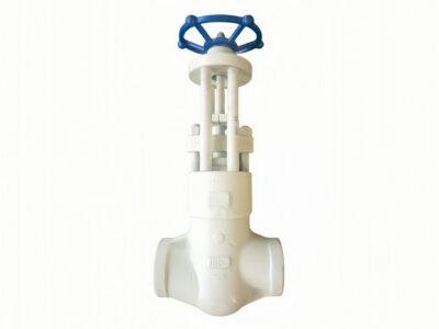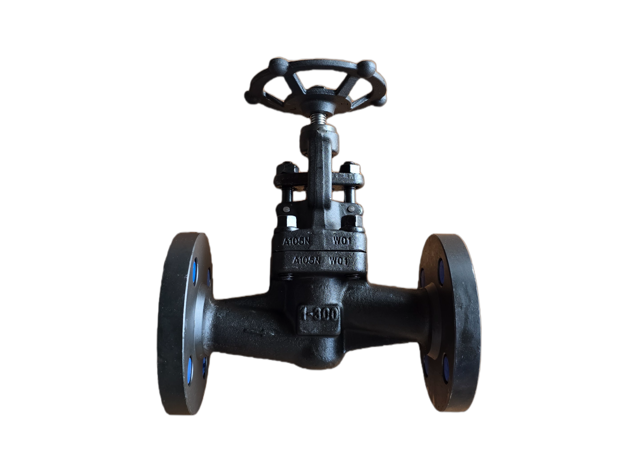
Globe Valve Close Die Forged— 1″ 300LB RF
Description
Technical Data Sheet
Closed Die Forged Globe Valve
Size & Class: 1″ 300LB RF
Body Material: ASTM A105N
1. General Description
This is a closed die forged, flanged globe valve. Both the body and bonnet are integrally forged from ASTM A105N normalized carbon steel using the closed die process. The valve features a rising stem and rotating handwheel for operation. The seating surfaces are overlayed with Stellite 6 hardfacing, providing excellent resistance to erosion and wear. It is suitable for precise flow regulation and tight shutoff in steam, water, oil, gas, and other general industrial media. Flanged ends comply with ASME B16.5 Raised Face (RF), Class 300.
2. Design Codes & Standards
Item Applicable Standard
Design & Manufacture API 602, BS 5352, ASME B16.34
Pressure-Temperature Rating ASME B16.34
End Connections ASME B16.5 (RF)
Face-to-Face Dimensions ASME B16.10 (Long Pattern)
Inspection & Testing API 598
Forging Standard ASTM A105 / A105N
3. Main Technical Specifications
Nominal Size: 1″ (DN25)
Pressure Class: Class 300 (300LB)
Connection Type: Flanged RF
Body/Bonnet Material: ASTM A105N (Closed Die Forged)
Disc Material: A105 + Stellite 6 Overlay
Body Seat Face: Integral Stellite 6 Overlay
Stem Material: ASTM A276 410 (13Cr) or 17-4PH
Packing: Flexible Graphite
Gasket: 304+Graphite Spiral Wound
Operation: Handwheel (Standard); electric/pneumatic actuators available as an option
Service Media: Steam, water, oil, natural gas, etc.
Temperature Range: -29 °C to +425 °C (-20 °F to +800 °F)
4. Materials of Major Parts
No. Part Name Material Standard
1 Body A105N ASTM A105
2 Bonnet A105N ASTM A105
3 Disc A105 + STL.6 Overlay ASTM A105
4 Seat Integral STL.6 Overlay —
5 Stem A276 410 (13Cr) / 17-4PH ASTM A276
6 Packing Flexible Graphite —
7 Bonnet Gasket 304+Graphite Spiral Wound —
8 Stud A193 B7 ASTM A193
9 Nut A194 2H ASTM A194
10 Handwheel Malleable Iron / Carbon Steel —
5. Principal Dimensions (1″ 300LB RF)
Symbol Description Value (mm) Value (inch)
L Face-to-Face Length 197 7.75″
D Flange Outer Diameter 124 4.88″
D1 Bolt Circle Diameter 88.9 3.50″
D2 Bolt Hole Diameter 19.1 0.75″
b Flange Thickness (incl. RF) 17.5 0.69″
H (approx.) Centerline to Top of Handwheel ~260 ~10.24″
HW Dia. Handwheel Diameter ~125 ~4.92″
Weight Approx. Weight ~7 kg —
Bolt Holes — 4 —
Note: Dimensions conform to ASME B16.10 and B16.5. The overall height is approximate. Final confirmed dimensions are subject to the approved drawing.
6. Performance Tests & Inspection
Shell Strength Test: 1.5 × Class 300 rated pressure (approx. 77.6 bar / 1125 psi), hold time ≥1 minute, no visible leakage or permanent deformation.
Seat Tightness Test (High/Low Pressure): High-pressure test at 1.1 × rated pressure (approx. 56.9 bar) water; low-pressure test at 0.6 bar pneumatic. Both meet API 598 zero leakage requirements.
Stem Operation: Handwheel operation is smooth, disc lifts and seats without sticking.
Visual & Dimensional Inspection: 100% visual inspection to ensure forging surfaces are free from defects such as cracks and laps. Critical dimensions are fully verified.
Material Certification (Optional): EN 10204 Type 3.1 material certificate and PMI spectral analysis available.
7. Installation & Maintenance Tips
Always ensure the flow direction matches the arrow cast on the body. Globe valves are typically designed for “flow under the seat” (low pressure under the disc). Reverse installation will affect sealing performance and service life.
The valve can be installed in horizontal or vertical pipelines, but the stem is recommended to be in a vertical upward position for ease of operation and maintenance.
Before initial high-temperature service, tighten bolts at ambient temperature. After reaching operating temperature, uniformly re-tighten the bonnet bolts to compensate for thermal expansion.
If abnormal resistance is encountered during handwheel operation, do not apply excessive force. Shut down and inspect for foreign objects or damaged seating surfaces.
Periodically check for leakage around the stuffing box. If necessary, gently and evenly re-tighten the packing gland or replace the packing under live-load conditions if permitted.
This technical data sheet is for selection reference only. The manufacturer reserves the right to change the design without prior notice. Final order shall be based on the approved drawing.