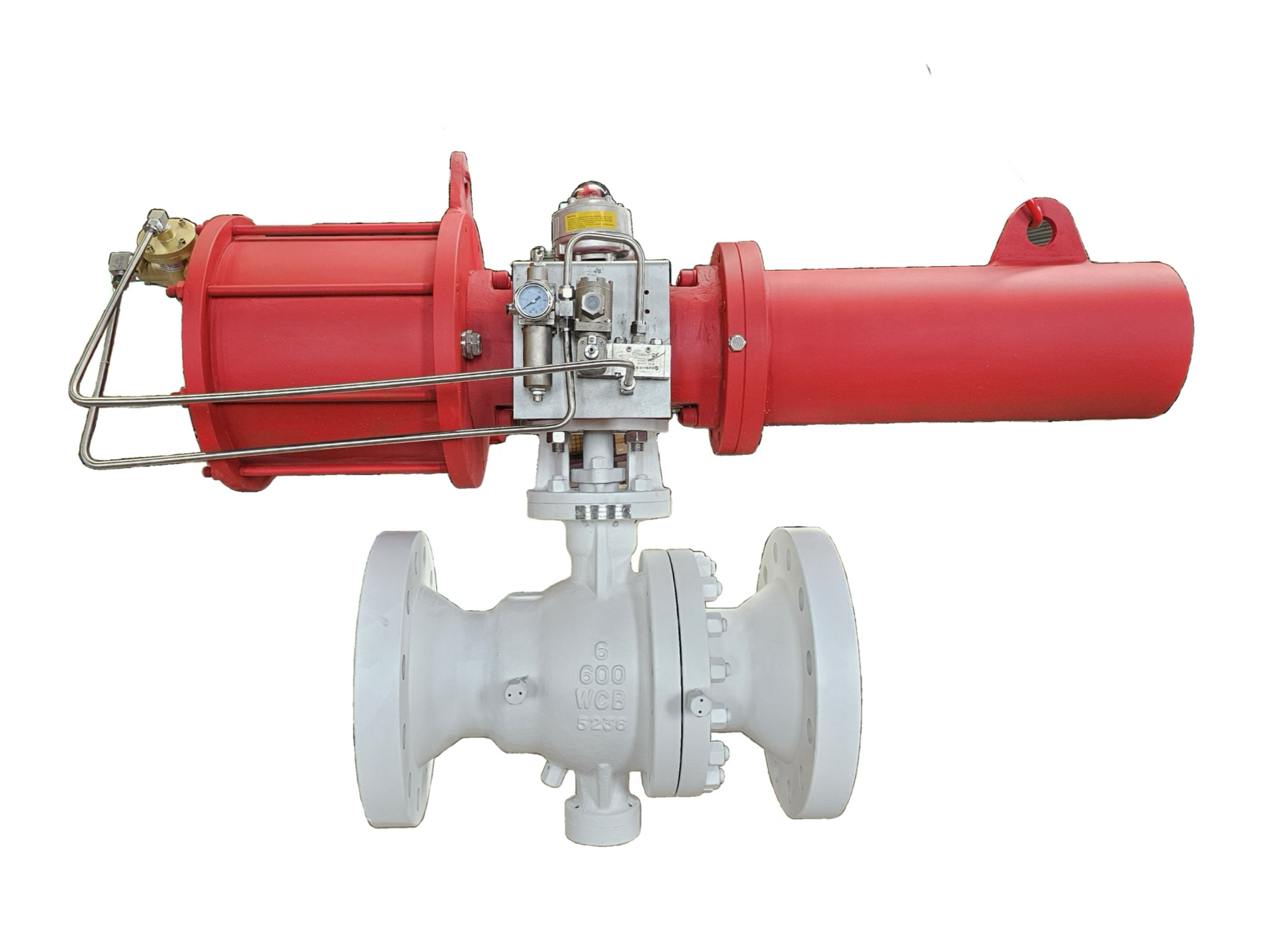
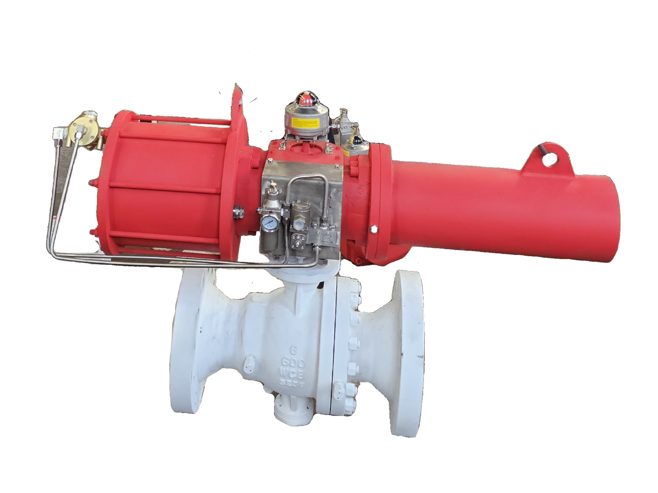
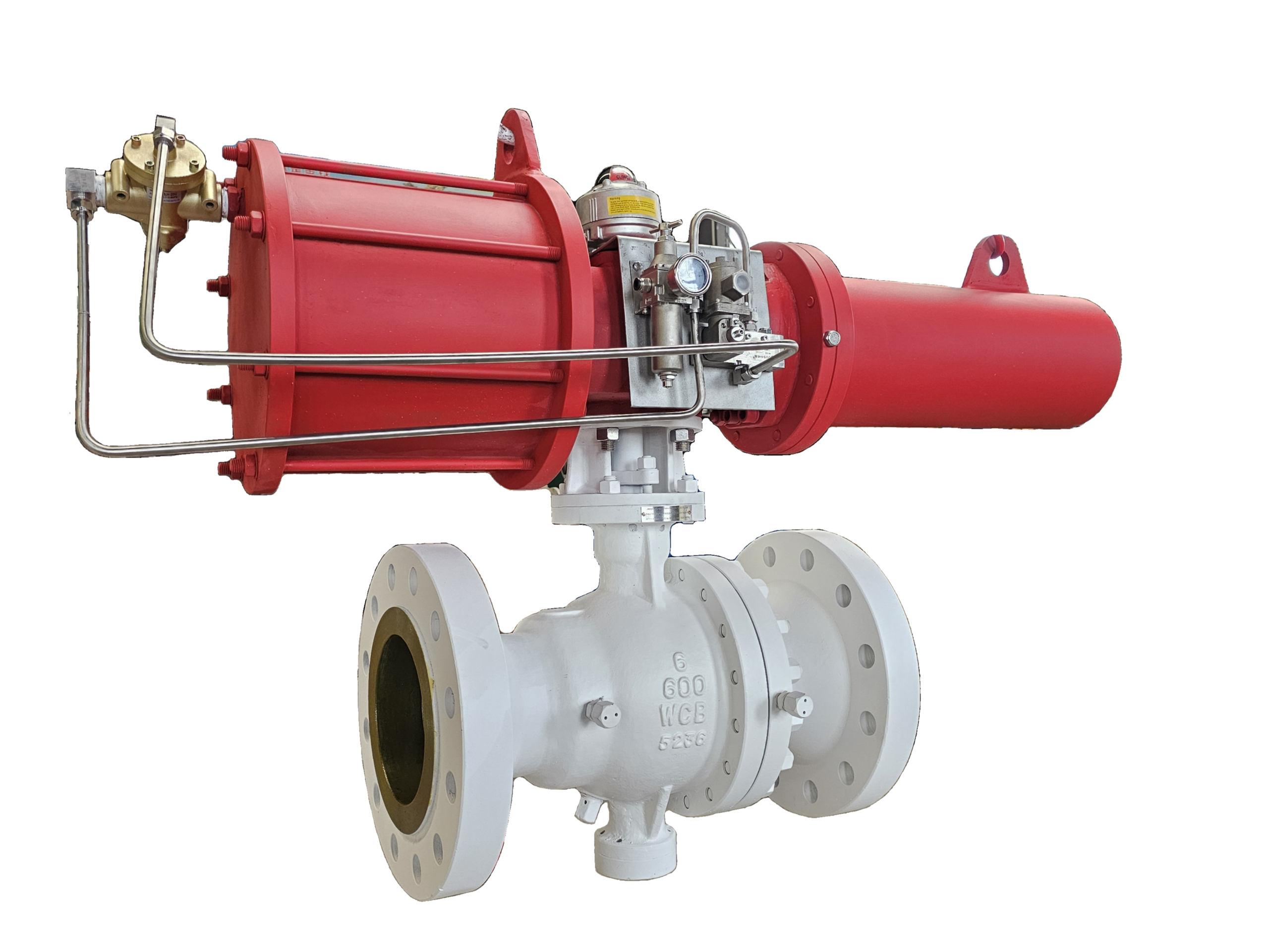
ESD (Emergency Shut-down ) Trunnion Ball Valves— 8″*6″ 600LB RF
Description
Technical Data Sheet – ESD Trunnion Ball Valve
Type: Emergency Shut-Down (ESD) | Size: 8″ x 6″ (Reducing) | Pressure Class: 600 LB
End Connection: Raised Face (RF) Flanged per ASME B16.5
1. General Description
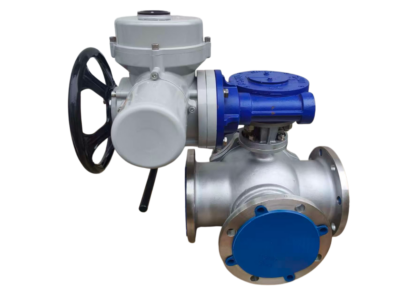
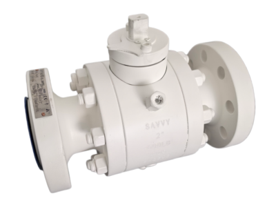
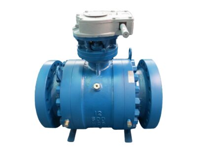
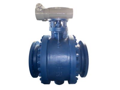
The 8″ x 6″ Class 600 ESD Trunnion Ball Valve is a high‑performance, safety‑critical valve designed for emergency shutdown applications in oil & gas pipelines, refineries, petrochemical plants, and offshore platforms. The trunnion‑mounted (fixed) ball ensures low torque and bubble‑tight shut‑off even under high differential pressure. The reducing port (8″ flanged ends with 6″ bore) allows flow reduction while maintaining pipeline compatibility. The valve is equipped with a fail‑safe actuation system (pneumatic / hydraulic / electro‑hydraulic) that closes rapidly upon loss of signal or power, meeting SIL (Safety Integrity Level) requirements.
2. Key ESD Features
Feature Description
Fail‑Safe Action Spring‑return pneumatic or hydraulic actuator – valve closes automatically on loss of power / signal
Closing Time ≤ 2 seconds (adjustable with flow control valve)
Partial Stroke Test (PST) Optional – allows in‑service partial stroke testing without interrupting process
Safety Integrity Level SIL 2 / SIL 3 capable (certifiable per IEC 61508)
Manual Override Hand pump or lever for manual operation during maintenance
Position Feedback Limit switches (open / close) + proximity sensors (ESD loop)
Redundant Solenoids Dual 24 VDC solenoids (1oo2 or 2oo2 configuration available)
3. Design & Construction Features
Feature Description
Body Construction 2‑piece or 3‑piece (depending on spec) – trunnion ball design
Ball Type Trunnion mounted (fixed) – reduced port (8″ end x 6″ bore)
Seat Design Double piston effect (DPE) seats – bidirectional, fire‑safe
Stem Design Blowout‑proof, anti‑static grounding, low emission packing (ISO 15848 optional)
End Connections RF flanges per ASME B16.5 Class 600
Fire Safety API 607 / ISO 10497 certified
Operation Pneumatic scotch‑yoke or hydraulic actuator with spring‑return (fail‑close)
4. Applicable Standards
Parameter Standard
Design & Manufacture API 6D, ASME B16.34, API 6DSS (for subsea, if required)
Face‑to‑Face Dimension ASME B16.10 (long pattern)
Flange Dimensions ASME B16.5 Class 600 RF
Pressure‑Temperature Rating ASME B16.34
Testing & Inspection API 598 (zero leakage) + ESD functional test
Fire Safety API 607 / ISO 10497
Fugitive Emissions ISO 15848‑2 (optional)
Actuator Standard ISO 5211 mounting pad
5. Material Specification (Standard Option – High Pressure Service)
Component Material
Body & End Cap ASTM A216 WCB (carbon steel) or ASTM A352 LCB (low temp)
Ball ASTM A182 F316 (stainless steel) – hard chrome plated or Tungsten Carbide coating for severe service
Trunnion / Stem ASTM A182 F316 (duplex or Inconel optional)
Seats PEEK (standard for high pressure) or PTFE with Inconel spring
Seat Springs Inconel X‑750
Stem Bearings Reinforced PTFE + bronze or carbon graphite
Packing Low emission graphite or PTFE (live‑loaded)
Gaskets Spiral wound (graphite + SS316)
Bolting ASTM A193 B7 / A194 2H (studs & nuts)
Coating Epoxy (blue RAL 5005) or 3‑layer corrosion protection for offshore
*For sour service (NACE), specify ASTM A216 WCB with NACE MR0175 / ISO 15156 compliance.*
6. Pressure‑Temperature Ratings (WCB Body – ASME B16.34 Group 1.1, Class 600)
Temperature Max Working Pressure
-20 to 100°F (-29 to 38°C) 1480 psig (102 bar)
200°F (93°C) 1350 psig (93 bar)
300°F (149°C) 1235 psig (85 bar)
400°F (204°C) 1130 psig (78 bar)
500°F (260°C) 1015 psig (70 bar)
PEEK seats allow continuous operation up to 500°F (260°C).
7. Dimensions & Weight (8″ x 6″ Class 600 RF, with Pneumatic Actuator)
Parameter Value
Face‑to‑Face (L) per ASME B16.10 559 mm (22.0 in)
Height (top of actuator) ≈ 950 mm (37.4 in) – depends on actuator
Flange O.D. (8″ Class 600 RF) 381 mm (15.0 in)
Bolt Circle Diameter 330 mm (13.0 in)
Number of Bolt Holes 12
Bolt Hole Diameter 25 mm (1.0 in)
Valve Body Weight (approx.) 210 kg (463 lb)
Actuator + Bracket Weight (approx.) 120 kg (265 lb)
Total Weight (approx.) 330 kg (728 lb)
Note: Dimensions for actuator vary by manufacturer. Provide actuator sizing based on required closing torque (typically 2x break torque).
8. Flow Coefficient (Cv) – Reduced Port (8″ x 6″)
Valve Configuration Cv (Water @ 60°F, 1 psi ΔP)
8″ x 6″ Reduced Port ≈ 550 – 650 (typical)
Exact Cv depends on ball bore geometry. Reduced port may cause higher pressure drop than full bore – verify with hydraulic analysis.
9. Operating Torque & Actuator Sizing (Class 600, PEEK seats)
Condition Break Torque (in‑lbs / Nm) Running Torque (in‑lbs / Nm)
Clean gas/liquid at 600 psi 4500 in‑lbs (508 Nm) 3000 in‑lbs (339 Nm)
At full differential pressure (1480 psi) 7200 in‑lbs (814 Nm) 5000 in‑lbs (565 Nm)
Actuator selection: Spring‑return pneumatic actuator must deliver at least 1.5x break torque at minimum supply pressure (e.g., 80 psi). Recommended actuator output: 12,000 in‑lbs (1356 Nm) spring torque.
10. ESD Actuator Specification (Typical Pneumatic Spring‑Return)
Parameter Value
Actuator Type Scotch‑yoke (pneumatic) – spring‑return fail‑close
Supply Pressure 80 – 120 psig (5.5 – 8.3 bar)
Solenoid Valves 2 x 24 VDC, 3/2 way, NAMUR mounting, Ex d / Ex ia
Closing Time (full stroke) ≤ 2 seconds (adjustable with speed control)
Opening Time Adjustable (typically 5 – 10 seconds)
Manual Override Hydraulic hand pump or lever
Limit Switches 2 x SPDT mechanical or proximity (Namur)
Partial Stroke Test (PST) Optional – integrated with solenoids and limit switches
For hydraulic fail‑close, specify hydraulic power unit (HPU) with accumulator and dump valve.
11. Testing & Validation
Test Standard Acceptance
Shell Hydrostatic 1.5 x rating (2220 psig) per API 598 No visible leakage
High‑Pressure Seat 1.1 x rating (1628 psig) per API 598 Zero bubbles
Low‑Pressure Air Seat 90 psig (0.6 MPa) Zero bubbles
Functional ESD Test Customer specific Valve closes within specified time
Partial Stroke Test (PST) As per ISA‑TR96.05 10‑20% stroke with full closure verified
Fire Test API 607 / ISO 10497 Pass
Fugitive Emissions ISO 15848‑2 < 100 ppm methane
12. Marking (per MSS SP‑25 + API 6D)
Manufacturer’s name / logo
8" – 600 LB (reducing: 8" x 6")
Body material: WCB (or LCB, CF8M)
API 6D
ESD marking (if required)
Heat number
Flow direction arrow (although bidirectional, arrow shown for reference)
CE / PED (if applicable)
13. ESD Loop Integration (Typical)
Component Function
ESD Logic Solver PLC / Safety Relay (SIL rated)
Pressure Transmitter / PSH Triggers shutdown on high pressure
Valve Positioner (optional) For controlled shut‑down (ESDV with partial stroke)
Solenoid Valves (2x) Redundant dump valves for actuator air supply
Limit Switches Feedback to logic solver (closed confirmation)
14. Ordering Information
To order an 8" x 6" Class 600 RF ESD Trunnion Ball Valve, please specify:
Valve size: 8" x 6" (reducing) – 8" flanged ends, 6" bore
Pressure class: 600 LB
Body material: WCB (carbon steel) or LCB (low temp) or CF8M (stainless)
Seat material: PEEK (standard for high pressure) or PTFE
End connection: RF flanges ASME B16.5
Actuation: Pneumatic spring‑return fail‑close (or hydraulic)
Solenoid voltage: 24 VDC (other voltages available)
Partial Stroke Test (PST): Yes / No
Fire‑safe certification: Yes (API 607)
NACE MR0175 / ISO 15156: Yes / No
Accessories: Limit switches, solenoid valves, quick exhaust valve, filter regulator, manual override
15. Important Notes
Trunnion design with double piston effect (DPE) seats provides bidirectional sealing and high pressure capability.
Reduced port (8" x 6") reduces flow capacity but maintains compactness. For full bore, specify 8" full port.
ESD valves must be tested regularly – partial stroke testing (PST) is strongly recommended to verify mechanical integrity without full closure.
Closing time must be coordinated with pipeline surge analysis to avoid excessive pressure rise (water hammer).
Always consult actuator manufacturer for exact torque requirements based on actual differential pressure and seat friction.
Disclaimer: This technical data sheet is for information purposes only. Final valve and actuator sizing must be validated by a qualified engineer based on site‑specific conditions (pressure, temperature, fluid, required safety response time, etc.). Refer to certified manufacturing drawings and test reports.
Issued by: [Your Company Name]
Revision: 1.0 / Date: [Current Date]
Let me know if you need a version with full bore (8" only) or additional details like subsea ESD or hydraulic actuation.