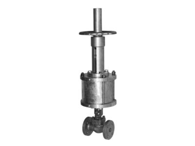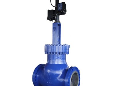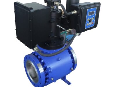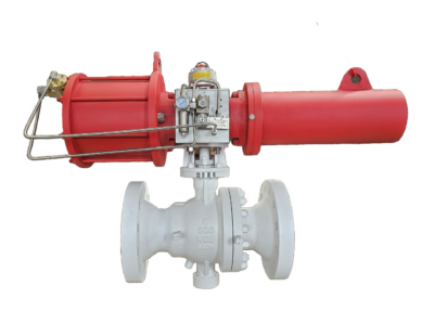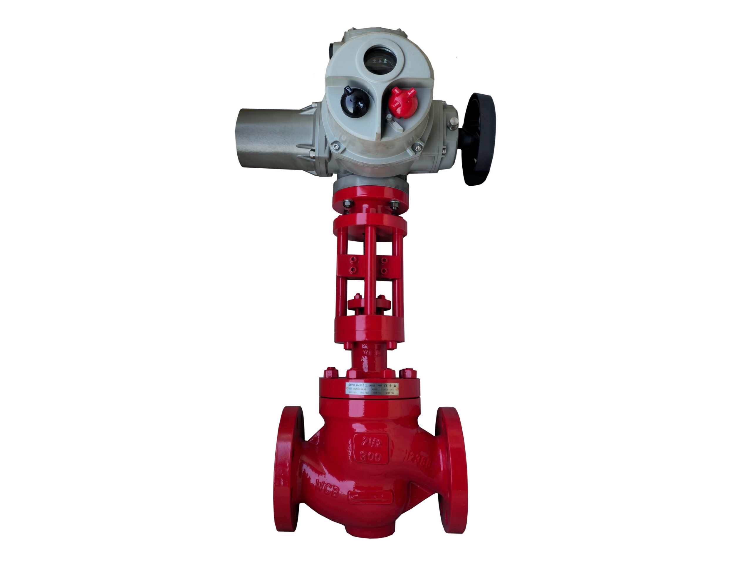
Control Valve Type Globe Balanced Caged
Description
TECHNICAL DATA SHEET
ELECTRIC ACTUATED MODULATING CONTROL VALVE
Type: Globe, Balanced, Cage-Guided
Actuation: Electric Multi‑Turn, Modulating Duty
Input Signal: 4–20 mA Analogue
Typical Sizes: DN15 – DN200 (½″ – 8″)
Pressure Class: ASME 150 / 300 / 600 (PN16 – PN100)
End Connections: Flanged (ASME B16.5 / EN 1092‑1), Butt‑Weld (ASME B16.25), or Screwed (NPT)
1. GENERAL DESCRIPTION
The control valve is a globe‑style, balanced, cage‑guided design intended for accurate modulating control of liquids, gases, and steam. The balanced plug construction, combined with a multi‑ported cage, significantly reduces the actuator thrust requirement and allows the valve to operate at high inlet pressures and high differential pressures with stable dynamic performance. The standard trim characteristic is equal percentage, with linear and quick‑opening available as options.
The valve is driven by an intelligent electric multi‑turn actuator accepting a 4–20 mA setpoint signal (with HART® communication as standard) and providing a 4–20 mA position feedback. The actuator can be configured for fail‑in‑place on loss of power, with optional fail‑safe (spring‑return) or battery backup operation. The assembly is supplied fully calibrated and factory‑tested.
2. APPLICABLE STANDARDS
| Parameter | Standard |
|---|---|
| Valve Design & Face‑to‑Face | ISA‑75.08.01 (Flanged), ASME B16.10, IEC 60534‑3‑1 |
| Flange Dimensions | ASME B16.5 / EN 1092‑1 |
| Butt‑Weld Ends | ASME B16.25 |
| Pressure‑Temperature Ratings | ASME B16.34 |
| Seat Leakage & Flow Testing | ANSI/FCI 70‑2, IEC 60534‑4 (inspection & testing) |
| Electric Actuator Standards | IEC 60534‑6‑2 (mounting), NEMA 250, IEC 60079 (explosion‑proof) |
| Signal & Communication | 4–20 mA, HART® 7 (standard), optional PROFIBUS PA/DP, Foundation Fieldbus, Modbus RTU |
| Functional Safety (optional) | IEC 61508 SIL 2/3 capable |
3. VALVE TECHNICAL SPECIFICATIONS
| Parameter | Value / Description |
|---|---|
| Valve Type | Globe, balanced, cage‑guided, single‑port |
| Body Size Range | DN15 to DN200 (½″ to 8″) |
| Pressure Class | ASME 150, 300, 600 (PN16, 40, 100) |
| End Connections | RF flanged (standard), RTJ, BW, SW, or NPT |
| Flow Characteristic | Equal percentage (standard), Linear, Quick‑opening |
| Flow Direction | Flow to open (FTO) – cage guided, balanced plug |
| Trim Type | Balanced with multi‑ported cage, clamped seat ring |
| Seat Leakage Class | ANSI/FCI 70‑2 Class IV (standard metal seat); Class V or VI (soft seat/trim) on request |
| Rangeability | 50:1 (equal percentage), 30:1 (linear) |
| Body Material | ASTM A216 WCC / WCB (carbon steel), ASTM A351 CF8M (316 SS), duplex, etc. |
| Trim Material (Std.) | 316 SS cage & plug with Stellite® hardfacing (seat & guide), 17‑4PH stem |
| Bonnet Type | Standard (‑29 to 200 °C), Extension (up to 400 °C), Cryogenic (‑196 °C) |
| Packing | PTFE‑V ring (standard), live‑loaded graphite (high temp), low‑emission certified (ISO 15848‑1) |
| Gaskets | Spiral wound 316L/Graphite |
4. ELECTRIC ACTUATOR SPECIFICATIONS
| Parameter | Value / Description |
|---|---|
| Actuator Type | Intelligent electric multi‑turn, modulating duty class D (per IEC 60034) |
| Power Supply | 24 V DC (standard), 100–240 V AC 1‑phase, 380–480 V AC 3‑phase (specify) |
| Input Control Signal | 4–20 mA (galvanically isolated) + HART® 7 |
| Feedback Signal | 4–20 mA position transmitter (passive/active) |
| Fail‑Safe Action | On loss of power: Stay‑put (standard). Optional: Fail‑close / fail‑open via spring‑return battery backup or spring mechanism |
| Communication | HART® 7 standard, optional fieldbus (Profibus PA, Foundation Fieldbus, Modbus RTU) |
| Local Interface | LCD display, 3‑button keypad, status LEDs. Multilingual menu. |
| Enclosure Rating | IP66 / IP67 (NEMA 4X) as standard |
| Explosion Protection (Option) | ATEX II 2 G Ex db eb IIC T4/T5, IECEx, CSA/FM, EAC |
| Duty Cycle | S9 100 % continuous modulation |
| Thrust/Torque Range | 2 kN to 50+ kN (sized to valve operating requirements) |
| Handwheel | Manual override handwheel (standard), lockable, declutchable |
| Cable Entries | 2 × M25 / ¾″ NPT (standard) |
| Ambient Temperature Range | –20 to +60 °C (‑40 °C optional) |
| Power Consumption | Depending on size – typically 30–150 W during operation |
| Control Unit Functions | Auto‑calibration, travel limits, adjustable dead band, split range, relay outputs, motor protections |
5. MATERIALS OF CONSTRUCTION (Typical)
| Part No. | Component | Carbon Steel Version | Stainless Steel Version |
|---|---|---|---|
| 1 | Body | ASTM A216 WCB/WCC | ASTM A351 CF8M (316 SS) |
| 2 | Bonnet | ASTM A216 WCB/WCC | ASTM A351 CF8M |
| 3 | Cage | ASTM A479 Type 316, heat treated | 316 SS with hard facing |
| 4 | Plug | ASTM A479 Type 316 + Stellite® | 316 SS + Stellite® |
| 5 | Seat Ring | ASTM A479 Type 316 + Stellite® | 316 SS + Stellite® |
| 6 | Stem | ASTM A564 17‑4PH (H1075) | ASTM A564 17‑4PH |
| 7 | Packing | PTFE V‑ring / Graphite | PTFE / Graphite |
| 8 | Gasket | SS316L + Graphite (spiral wound) | SS316L + Graphite |
| 9 | Actuator Housing | Aluminum alloy, epoxy coated | (same) |
| 10 | Mounting Bracket | Carbon steel, painted / SS | Stainless Steel |
Trim materials may be upgraded to full Inconel® 718, duplex, or alloy 6 (Stellite®) for severe service. Hardfacing on seating surfaces and guide areas is standard.
6. TYPICAL FLOW COEFFICIENTS (Cv) & TRAVEL – Equal Percentage Cage
| NPS | DN | Trim Travel (mm) | Nominal Cv Range (Full Capacity) |
|---|---|---|---|
| ½″ | 15 | 15 | 0.12 – 4.0 |
| ¾″ | 20 | 15 | 4.0 – 7.0 |
| 1″ | 25 | 15 | 7.0 – 12.0 |
| 1½″ | 40 | 20 | 12.0 – 25.0 |
| 2″ | 50 | 20 | 25.0 – 50.0 |
| 3″ | 80 | 30 | 50.0 – 110.0 |
| 4″ | 100 | 30 | 110.0 – 200.0 |
| 6″ | 150 | 40 | 200.0 – 420.0 |
| 8″ | 200 | 50 | 420.0 – 700.0 |
Reduced trims for lower Cv values are available. Actual Cv values may vary based on specific cage design and pressure class.
7. DIMENSIONS & WEIGHTS (Flanged, ASME 300, ISA‑75.08.01 Face‑to‑Face)
| DN | NPS | Face‑to‑Face L (mm) | Height H (mm) (valve + actuator) | Approx. Weight (kg) |
|---|---|---|---|---|
| 15 | ½″ | 184 | 550 | 22 |
| 20 | ¾″ | 184 | 560 | 25 |
| 25 | 1″ | 184 | 580 | 28 |
| 40 | 1½″ | 222 | 650 | 40 |
| 50 | 2″ | 254 | 710 | 55 |
| 80 | 3″ | 298 | 820 | 90 |
| 100 | 4″ | 352 | 950 | 145 |
| 150 | 6″ | 451 | 1150 | 280 |
| 200 | 8″ | 543 | 1350 | 480 |
Dimensions are typical for a carbon steel body with standard electric actuator. Exact dimensions depend on actuator selection and options; consult certified outline drawing.
8. TESTING & INSPECTION
| Test | Medium | Test Pressure / Procedure | Acceptance Criteria |
|---|---|---|---|
| Shell Strength (Body) | Water | 1.5 × Max. Design Pressure (ASME B16.34) | No visible leakage |
| Seat Leakage | Water / Air | ANSI/FCI 70‑2 Class IV (metal) or V/VI (soft) | Within leakage rate per standard |
| Actuator Function & Calibration | – | 4–20 mA input/output, limit switches, handwheel, display | Error ≤ 0.5 % of span, dead band adjustable |
| Stroke Test & Response Time | – | Full travel open‑close at rated speed | Within actuator specifications |
| Insulation & Dielectric Test | – | As per actuator manufacturer / IEC 61010 | No insulation breakdown |
| Coating & Painting | – | Visual & dry film thickness measurement | Per specification (typically epoxy 250 µm DFT) |
| Documentation | – | EN 10204 3.1 material certs, test reports, calibration cert | Traceable to heat numbers |
Additional optional tests: PMI, cryogenic/fugitive emission type testing, SIL verification, full functional safety testing.
9. OPTIONS & ACCESSORIES
-
Trim & Cage Configurations: Whisper Trim™ (low noise), anti‑cavitation multi‑stage trim, erosion‑resistant trim (tungsten carbide).
-
Seat Leakage Upgrade: Class V (PTFE/PEEK insert) or Class VI (soft seal) for bubble‑tight shut‑off.
-
End Connections: RTJ flanges (Class 900/1500), socket‑weld, butt‑weld.
-
Fail‑Safe Package: Battery backup system (UPS) or spring‑return electric actuator.
-
Positioner Integration: The actuator integrates smart positioner functions (no external positioner required), but can be supplied with a separate digital positioner for retrofits.
-
Networking & Diagnostics: Advanced diagnostics, partial stroke testing, predictive maintenance alerts via HART®/Fieldbus.
-
Mounting Kit for Field Installation: Yoke and stem connector kit for mounting on existing valve body.
-
Certifications: ATEX/IECEx explosion proof, SIL 2/3, PED 2014/68/EU, CRN, NACE MR0175/ISO 15156.
10. ORDERING INFORMATION
To specify this control valve, please provide the following minimum data:
-
Valve type: Globe, Balanced, Cage-Guided
-
Size: DN _____ (NPS _____)
-
Pressure class: ANSI Class _____ / PN _____
-
Body material: Carbon Steel / 316 SS / Duplex / Other
-
Trim material & characteristic: Equal % / Linear / QC
-
Process medium, temperature & inlet/outlet pressure
-
Flow rate (min, normal, max) & required Cv
-
Seat leakage class: Class IV / V / VI
-
Actuator power supply: 24 V DC / 110‑240 V AC / 380‑480 V AC
-
Control signal: 4–20 mA + HART® (standard)
-
Fail‑safe action on loss of power: Stay‑put / Fail‑close / Fail‑open
-
Hazardous area classification & enclosure rating (if required)
-
Accessories & special requirements
This technical data sheet represents a typical high‑performance balanced caged control valve assembly. The manufacturer will perform a full Cv and actuator sizing calculation based on service conditions to guarantee optimal performance and control stability.