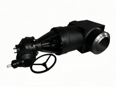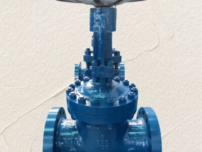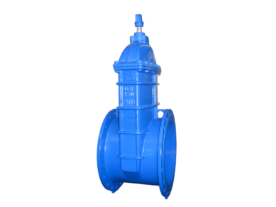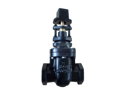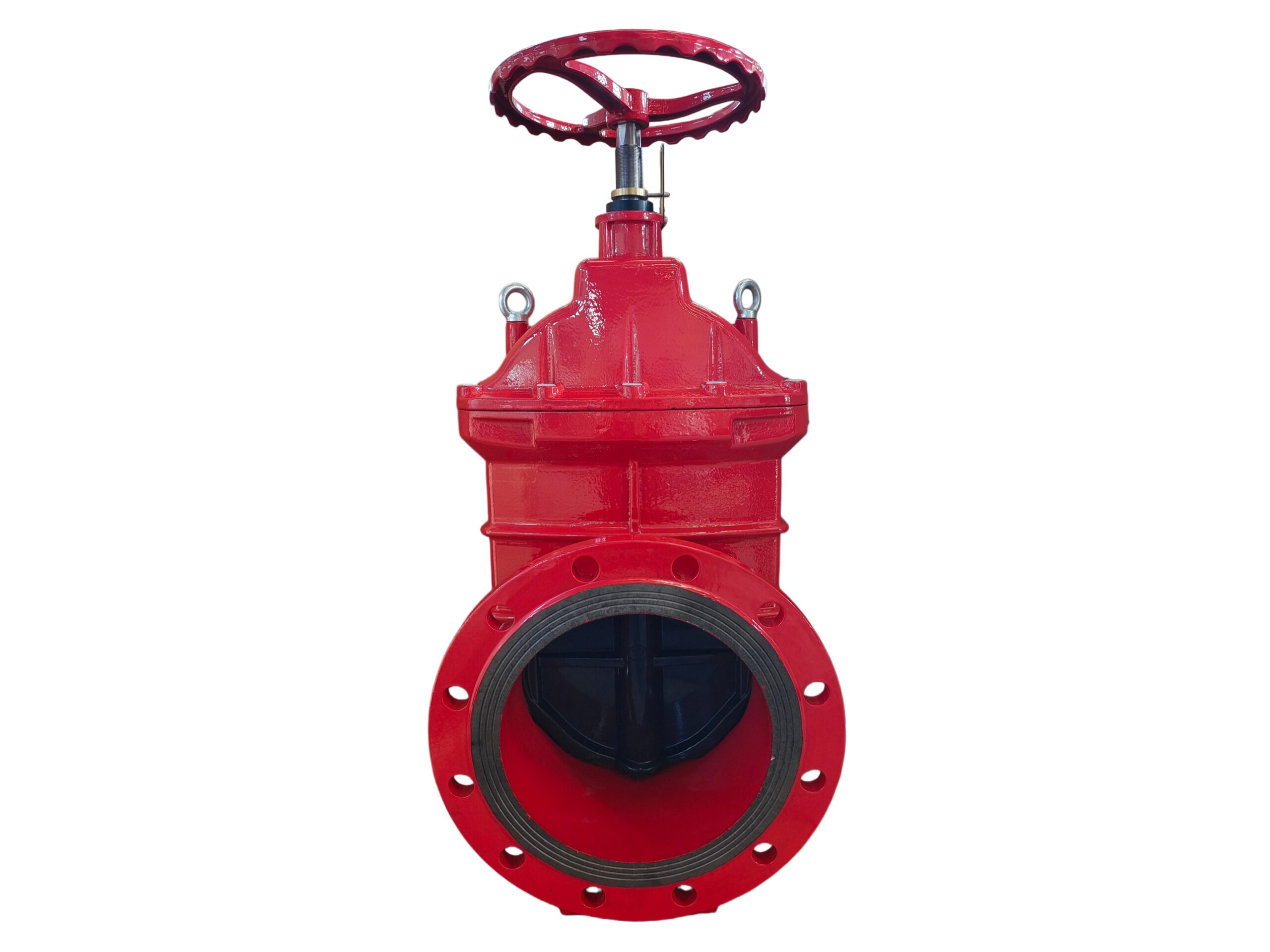
Non-Rising Stem (NRS) Resilient-Seated Gate Valve
Description
TECHNICAL DATA SHEET
Non-Rising Stem (NRS) Resilient-Seated Gate Valve
Ductile Iron Body, EPDM Encapsulated Wedge
| Document Ref. | DI-NRS-RSGV-EPDM-EN |
|---|---|
| Revision | 01 |
| Date | 2026-07-09 |
1. GENERAL DESCRIPTION
The Ductile Iron Non-Rising Stem (NRS) Resilient-Seated Gate Valve features a fully encapsulated EPDM wedge for bubble-tight shutoff in both directions. The non-rising stem design makes it ideal for underground installation, pump stations, and confined spaces where vertical space is limited. The robust ductile iron construction combined with high-performance elastomer seats provides long service life, zero leakage, and low operating torque. It is designed primarily for water, wastewater, and neutral fluids.
2. DESIGN FEATURES
-
Non-Rising Stem (NRS): Compact design, stem does not protrude when opening, perfect for buried service and valve pits.
-
Full-Bore Clear Way: No recesses in the body; eliminates debris accumulation and ensures full, unobstructed flow.
-
Fully Encapsulated Wedge: Ductile iron core completely vulcanized with EPDM rubber, no exposed iron on the sealing faces, providing excellent corrosion resistance and bubble-tight seal.
-
Triple O-Ring Stem Sealing: Maintenance-free stem seal achieved through multiple low-torque EPDM O-rings. No traditional gland packing adjustments required.
-
Built-in Thrust Bearing: Low-friction brass stem nut with integral thrust collar reduces operating torque.
-
Fusion Bonded Epoxy Coating: Internal and external surfaces coated with fusion bonded epoxy (FBE) for superior corrosion protection and potable water compatibility.
3. APPLICABLE STANDARDS
| Category | Standard |
|---|---|
| Design & Manufacturing | BS 5163 / EN 1171 (Resilient-Seated Gate Valves for Water Supply) |
| Face-to-Face Dimensions | EN 558-1 Series 14 (Short Pattern, DIN 3202 F4) |
| Flange Drilling | EN 1092-2 PN16 |
| Testing & Inspection | EN 12266-1 (Rate A – Zero Leakage) |
| Coating | AWWA C550 / WIS 4-52-01 (Internal & External FBE) |
| Drinking Water Approvals | WRAS / ACS / NSF/ANSI 61 (Optional, depends on coating formulation) |
4. TECHNICAL SPECIFICATIONS
| Parameter | Value |
|---|---|
| Nominal Diameter (DN) | DN50 – DN300 (Full range up to DN1200 available) |
| Nominal Pressure (PN) | PN16 (16 bar) |
| Maximum Working Pressure (WOG) | 16 bar (232 psi) @ 20°C |
| Shell Test Pressure | 24 bar (1.5 x PN) |
| Seat Test Pressure | 17.6 bar (1.1 x PN) |
| Leakage Rate | Zero leakage (EN 12266-1 Rate A) |
| Temperature Range (EPDM) | -10 °C to +80 °C (briefly +100 °C) |
| Flow Direction | Bi-directional |
| Operation | Manual Handwheel (Standard), Gearbox (Optional for ≥ DN200) |
5. BILL OF MATERIALS (BOM)
| No. | Component | Material | Standard / Grade |
|---|---|---|---|
| 1 | Body | Ductile Iron | EN GJS-500-7 / ASTM A536 65-45-12 |
| 2 | Bonnet | Ductile Iron | EN GJS-500-7 / ASTM A536 65-45-12 |
| 3 | Wedge Core | Ductile Iron | EN GJS-500-7 / ASTM A536 65-45-12 |
| 4 | Wedge Elastomer | EPDM | Bio-resistant, WRAS approved formulation |
| 5 | Stem | Stainless Steel | AISI 420 (1.4021) or AISI 304 (1.4301) |
| 6 | Stem Nut | Brass / Bronze | CuZn39Pb3 (CW614N) or C89835 |
| 7 | Bonnet Gasket | EPDM | – |
| 8 | Stem O-Rings (3 pcs) | EPDM | – |
| 9 | Thrust Washer | PTFE / Brass | – |
| 10 | Wiper Ring | NBR | – |
| 11 | Bolts & Nuts | Stainless Steel | A2-70 / A4-70 (Optional Zinc Plated CS) |
| 12 | Handwheel | Ductile Iron | EN GJS-500-7 (FBE Coated) |
| 13 | Snap Ring / Retainer | Stainless Steel | AISI 304 |
6. DIMENSIONS (PN16, Short Pattern)
| DN | Face-to-Face L (mm) | Center to Handwheel Top H ≈ (mm) | Handwheel Diameter D (mm) | Approx. Weight (kg) |
|---|---|---|---|---|
| 50 | 150 | 270 | 200 | 9 |
| 65 | 170 | 290 | 200 | 11 |
| 80 | 180 | 330 | 200 | 13 |
| 100 | 190 | 380 | 250 | 17 |
| 125 | 200 | 430 | 250 | 22 |
| 150 | 210 | 500 | 300 | 28 |
| 200 | 230 | 610 | 350 | 43 |
| 250 | 250 | 740 | 400 | 66 |
| 300 | 270 | 850 | 450 | 92 |
Note: Dimensions are for standard manual handwheel operation. For gearbox or extended spindle variants, consult factory. H is measured from pipe centerline to top of handwheel in closed position.
7. TESTING & INSPECTION
Every valve undergoes the following tests in accordance with EN 12266-1:
-
Shell Pressure Test: 24 bar for 60 seconds minimum (Water).
-
Seat Leakage Test: 17.6 bar applied alternately from each side, zero visible leakage permitted for resilient seated valves.
-
Pneumatic Test: Available upon request (typically 6 bar air under water).
-
Coating Inspection: Dry film thickness (DFT) measured (min 250 µm), holiday/high-voltage spark test at 1000V.
8. COATING DETAILS
-
Type: Fusion Bonded Epoxy (FBE)
-
Color: RAL 5017 (Traffic Blue) – Standard. (RAL 9005 Black or other colors optional)
-
Minimum Thickness: 250 μm internal and external.
-
Approvals: Suitable for drinking water per WRC/BS 6920, WRAS, ACS where certified material is used.
9. ACCESSORIES & OPTIONS
-
Gear Operator (Gearbox): Recommended for DN250 and above (or as specified) to reduce manual torque.
-
Bypass Arrangement: Available for large diameters to equalize pressure before opening.
-
Position Indicator: Rising plate or indicator post.
-
Extended Spindle / Stem Extension: For buried service, includes extension stem and square operating cap.
-
Limit Switches: Mechanical or proximity type for remote position monitoring.
-
Floor Stand: Pedestal support for above-ground installation.
-
Body Drain Plug: Optional tapped and plugged drain in the body (standard on some sizes).
10. NOTES
-
EPDM seat is suitable for water, wastewater, and some mild chemicals. It is not suitable for hydrocarbons, mineral oils, or petroleum-based fluids. For oil service, please specify NBR encapsulated wedge.
-
Continuous operation near the maximum temperature limit may shorten the service life of the elastomer seals.
-
This technical data sheet supersedes all previous versions for the specified model. The manufacturer reserves the right to modify design and specifications without prior notice in the interest of product improvement.
For critical dimensions, certified as-built drawings, or specific material certificates (EN 10204 3.1/3.2), please contact the manufacturer.