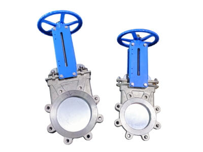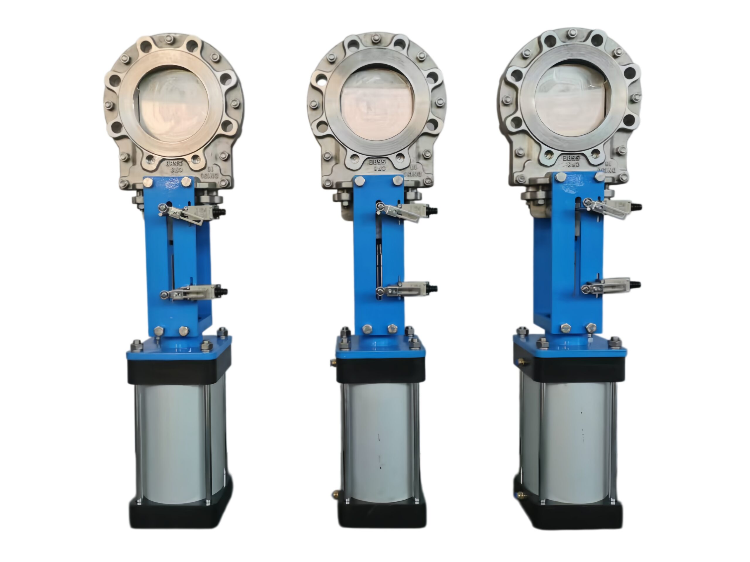
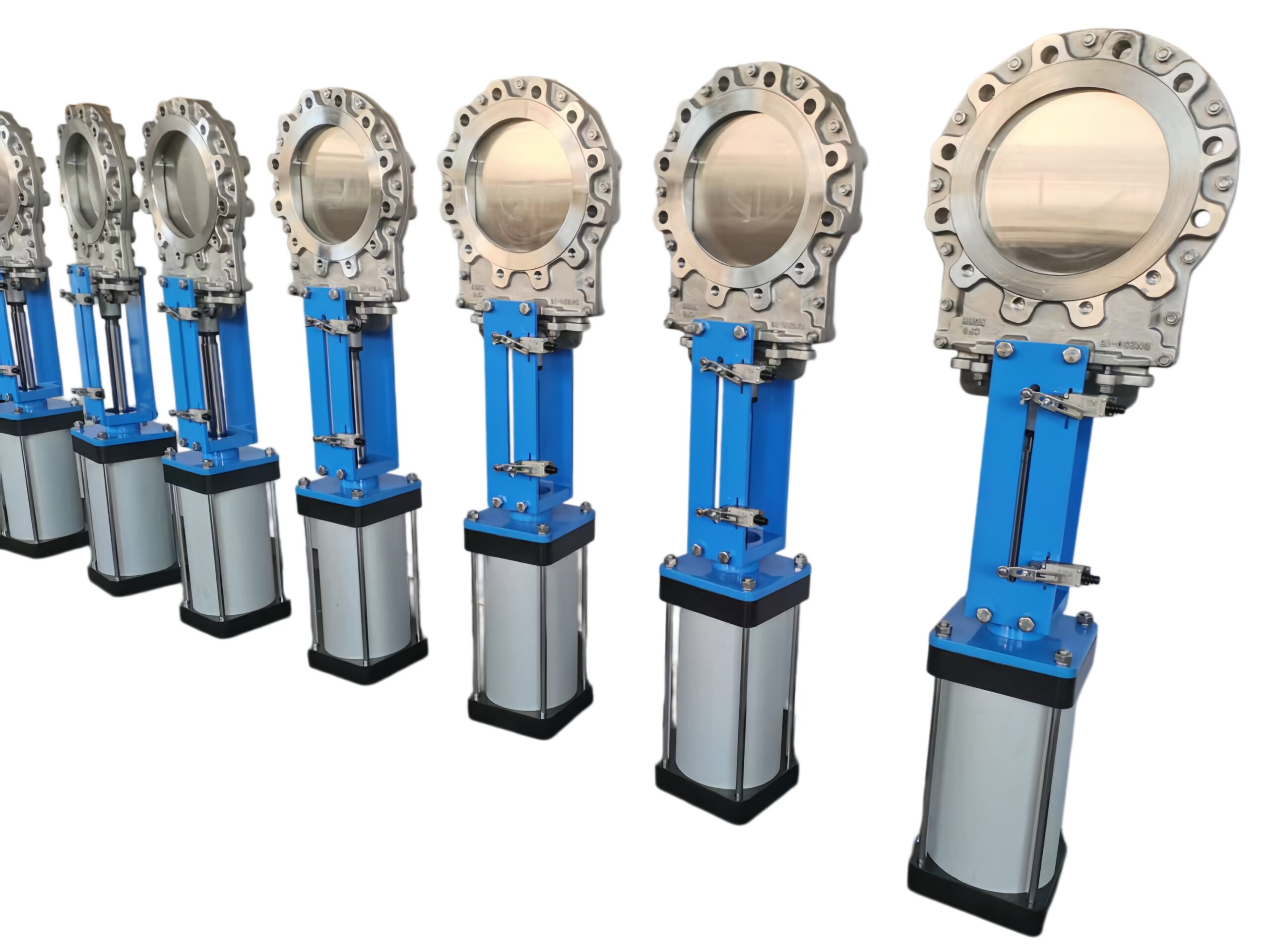
Pneumatic Actuated Knife Gate Valve
Description
Technical Data Sheet
Product: Pneumatic Actuated Knife Gate Valve
Construction: 316SS Body & Gate, Metal Seated, Uni-Directional Seal
Operation: Double Acting Pneumatic Cylinder with Limit Switch Box
1. General Description
This valve is a bi-directional body knife gate valve designed for on-off and isolation service in heavy slurries, pulp & stock, wastewater, and dry bulk handling. The valve utilizes a one-piece, fully machined 316L/316 stainless steel body and a mirror-polished 316 stainless steel gate. The primary seal is a metal-to-metal contact between the gate and the integral metal seat, providing a positive shutoff in a single (preferred) flow direction. A secondary packing gland provides an external stem seal. The valve is automated by a double-acting pneumatic cylinder and supplied with mechanical/inductive limit switches to confirm fully open and fully closed positions.
2. Design, Manufacturing & Inspection Standards
-
Valve Design: MSS SP-81 (Stainless Steel Knife Gate Valves)
-
Pressure Rating: ASME Class 150 / PN10 / PN16 (This sheet uses Class 150)
-
Face-to-Face: MSS SP-81 / ISO 5752 Series 20 (Short Pattern)
-
Flange Compatibility: Fits between ASME B16.5 Class 150 flanges (wafer type)
-
Testing & Inspection: MSS SP-81, Shell & Seat Leakage
-
Pneumatic Actuator: ISO 6432 / ISO 15552 (Tie-rod cylinder design)
-
Limit Switches: IEC 60947-5-1, IP67/NEMA 4X
-
Marking: MSS SP-25
3. Technical Parameters
| Parameter | Specification |
|---|---|
| Nominal Size | DN50 – DN600 (2″ – 24″) |
| Pressure Class | Class 150 (PN20) |
| Valve Body Material | ASTM A351 CF8M (SS316) or ASTM A240 316L (fully fabricated) |
| Gate Material | ASTM A240 316 / 316L, polished, beveled edge |
| Seat Type | Integral Metal Seat (SS316 body seat, unpainted) |
| Seal Direction | Single direction, bubble-tight in preferred flow (arrow on body) |
| Packing | PTFE-impregnated synthetic fiber (standard), Graphite (optional) |
| Gland / Packing Follower | SS316 |
| Yoke / Pillar | SS316 (integrally cast or bolted) |
| Connection Type | Wafer (fits between companion flanges) |
| Actuator Type | Double Acting Pneumatic Cylinder |
| Air Supply Pressure | 5.5 bar (80 psi) standard; Maximum 10 bar (145 psi) |
| Cylinder Material | Aluminum alloy, hard anodized, with SS304 tie rods (SS316 cylinder on request) |
| Solenoid Valve | 5/2 way, Namur interface, 24VDC / 110VAC / 220VAC (to be ordered separately or included) |
| Limit Switches | 2 x SPDT mechanical or P+F inductive sensors in IP67 enclosure, visual position indicator |
| Open/Close Time | < 2 seconds per 100mm bore (typical, depending on cylinder size) |
| Leakage Rate (Preferred Dir.) | MSS SP-81 Metal Seat: Leakage rate ≤ 40 ml/min per inch of DN (Class IV equivalent) |
| Temperature Range (Standard) | -29°C to +180°C (-20°F to +356°F) with PTFE packing |
| Coating | None (bare SS316 valve). Cylinder: standard industrial coating. |
4. Materials of Main Parts
| No. | Part Name | Material |
|---|---|---|
| 1 | Body | ASTM A351 CF8M (SS316) or A240 316L |
| 2 | Gate | ASTM A240 316L, hardened edge optional |
| 3 | Integral Metal Seat | Body machined (SS316) |
| 4 | Packing Gland | ASTM A276 SS316 |
| 5 | Packing Set | PTFE impregnated aramid / Graphite |
| 6 | Yoke / Pillars | SS316 |
| 7 | Stem (Piston Rod) | SS316 (cylinder side) or SS316 extension |
| 8 | Clevis / Connector | SS316 |
| 9 | Cylinder Body | ASTM 6063 Aluminum, hard anodized |
| 10 | Piston Rod | Hard chrome plated carbon steel (SS316 on request) |
| 11 | Limit Switch Box | IP67 polycarbonate / aluminum housing, with visual beacon |
| 12 | Fasteners | SS316 |
5. Main Dimensions and Weights (Class 150, Wafer, Standard Pneumatic Cylinder)
Dimensions include double-acting cylinder and standard limit switch box. Air supply 5.5 bar.
| DN | Size (in) | Face-to-Face L (mm) | Height H (mm) (Closed, approx.) | Cylinder Ø (mm) | Approx. Weight (kg) |
|---|---|---|---|---|---|
| 50 | 2 | 48 | 510 | 63 | 8 |
| 80 | 3 | 51 | 600 | 80 | 13 |
| 100 | 4 | 51 | 680 | 100 | 18 |
| 150 | 6 | 57 | 830 | 125 | 32 |
| 200 | 8 | 70 | 980 | 160 | 52 |
| 250 | 10 | 70 | 1140 | 200 | 78 |
| 300 | 12 | 76 | 1300 | 200 | 115 |
| 400 | 16 | 89 | 1600 | 250 | 210 |
| 500 | 20 | 100 | 1960 | 320 | 380 |
| 600 | 24 | 100 | 2260 | 400 | 560 |
Note: Dimensions and weights are typical for a standard double-acting cylinder at 5.5 bar supply. For larger actuators, high-pressure cylinders, or specific accessories, final certified drawings will be provided. Flange drilling matching is per standard.
6. Pressure–Temperature Ratings (Body: CF8M / 316SS, Metal Seat, PTFE Packing)
Based on ASME B16.34 for Group 2.2 material (316/CF8M), limited by packing and seal integrity.
| Temperature (°C) | Max. Working Pressure (bar) |
|---|---|
| -29 to 38 | 19.6 |
| 50 | 19.2 |
| 100 | 17.7 |
| 150 | 15.8 |
| 180 | 14.0 |
Test Pressures (Ambient Water)
Shell Test: 29.4 bar (1.5 x CWP)
Seat Test (Preferred direction): MSS SP-81 metal seat criteria.
7. Installation and Maintenance Notes
-
Flow Direction: The valve must be installed with the arrow on the body pointing in the desired sealing direction. Reverse flow may cause seat leakage.
-
Flange Gaskets: Use full-face compatible gaskets between the valve body and mating flanges (PTFE, EPDM, or fiber depending on service).
-
Alignment: The gate must be completely clear of the line bore before opening to prevent damage. Ensure no misalignment of mating flanges that could bind the gate.
-
Pneumatic Connection: Connect clean, dry, lubricated air to the 1/4″ NPT ports. Use a pilot-operated check valve if the valve must fail-safe in the event of air loss (note: a single-acting spring-return actuator is required for fail-safe, not double-acting).
-
Limit Switch Adjustment: Factory set for full open/close. The cams inside the switch box can be re-adjusted if necessary.
-
Maintenance: The gland packing is externally adjustable. Tighten the gland nuts evenly if stem leakage occurs. Replace packing set with the valve in the closed position and line depressurized.
-
Gate Replacement: The gate can be extracted from the body for polishing or replacement without removing the valve from the pipeline (full bore opening required).
8. Ordering Information
Please specify the following when ordering:
-
Nominal size and pressure class (e.g., DN150 Class 150)
-
Valve body and gate material (SS316 / CF8M)
-
Seat type (Metal seated, single direction)
-
Packing material (PTFE or Graphite)
-
Pneumatic actuator: Double Acting, air supply pressure available (e.g., 6 bar)
-
Limit switch type: Mechanical SPDT or Proximity (NAMUR, 2-wire/3-wire)
-
Solenoid valve voltage (if integrated): 24VDC / 110VAC / 220VAC
-
Any special cleaning or certification (e.g., degreasing for oxygen service, ATEX zone for limit switches)
-
Media type and operating temperature
If a spring-return fail-safe actuator, a bevel gear operator, or a different connection (flanged/lugged) is required, please request a separate datasheet.