Y Pattern Strainer in Cast Iron
Description
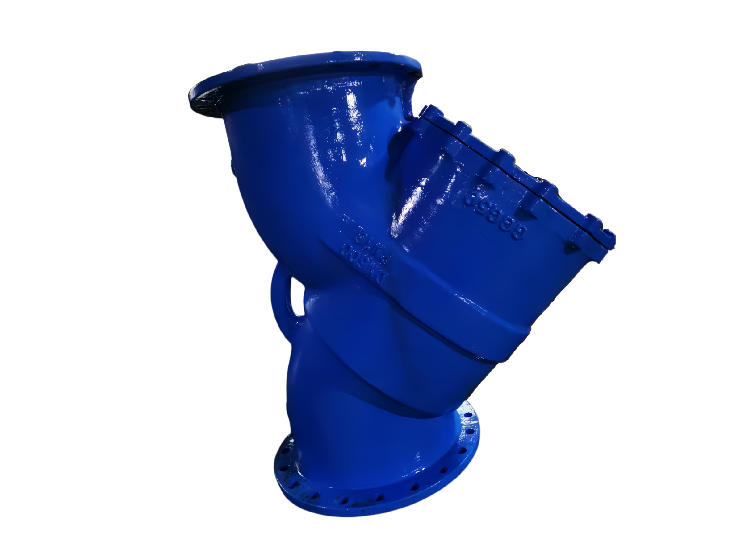
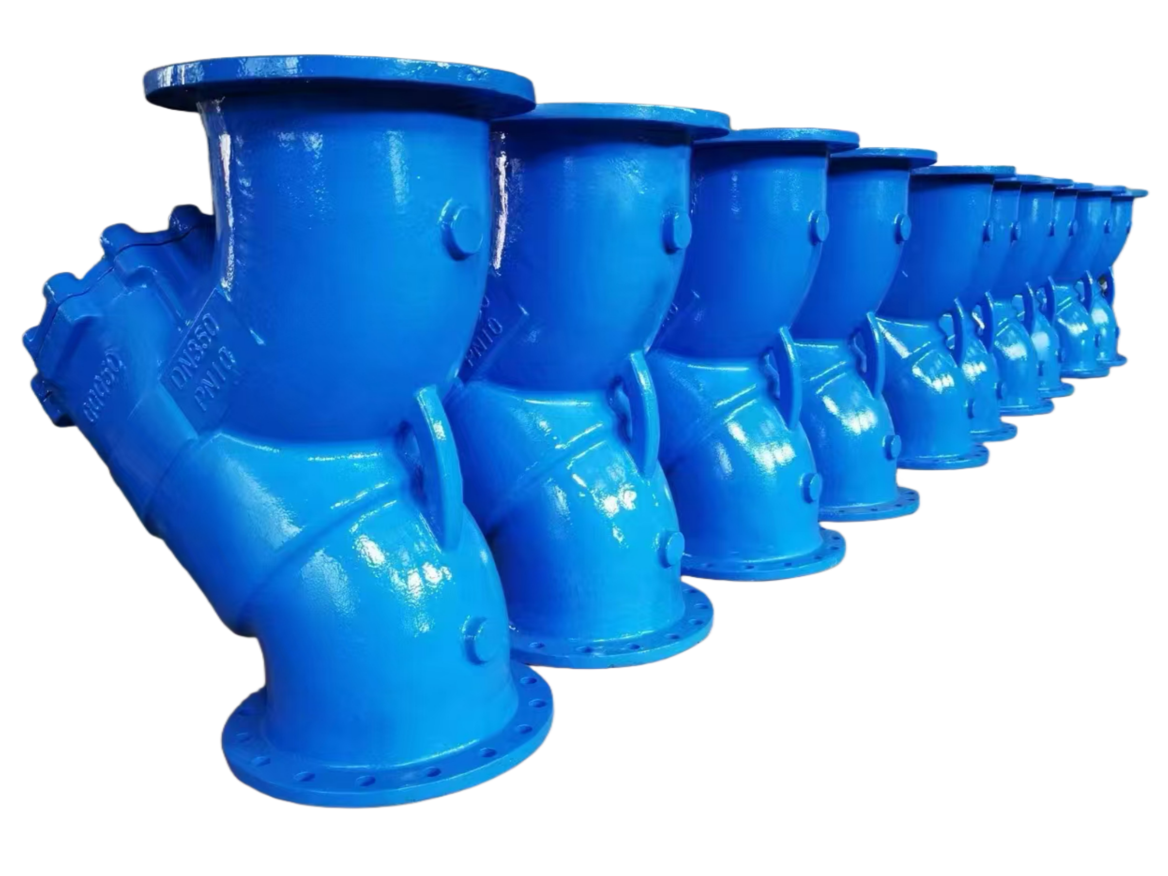
Y-Pattern Strainer (Cast Iron)
Technical Data Sheet
1. Product Overview
This series of Cast Iron Y-Pattern Strainers is designed to remove solid particulate impurities from pipeline media, effectively protecting downstream pumps, valves, instruments, and other equipment from damage caused by weld slag, rust, sand, and other foreign matter. The body and cover are manufactured from high-quality cast iron, providing a compact structure, low flow resistance, and high dirt-holding capacity. Widely used in water supply and drainage, HVAC, fire protection, irrigation, and general industrial fluid systems. The screen is available in various materials and filtration ratings and can be quickly removed for cleaning or replacement, ensuring easy maintenance.
2. Design Features & Benefits
Compact Y-Pattern Design: The Y-shaped flow path minimizes pressure loss while maximizing the filtration area with the screen positioned at an incline.
Cast Iron Body: Manufactured from high-strength gray cast iron (HT200/250 or ASTM A126 Class B), offering excellent economy, high rigidity, and superior vibration damping.
Removable Screen: The screen assembly is secured by a cover. Simply loosen the blowdown plug or remove the cover to extract the screen for cleaning without removing the entire strainer from the pipeline.
Versatile Screen Options: Available in stainless steel perforated plate or dual-layer mesh construction. Filtration ratings from mesh to millimeter sizes are available, with custom options supported.
Long-Life Sealing: Non-asbestos fiber gaskets or reinforced rubber gaskets are used between the cover and body, ensuring reliable sealing for a wide range of media.
Threaded Blowdown Connection: The bottom is standardly equipped with a plug, and a blowdown ball valve can be installed to enable online draining.
Flanged Connection: Flange drilling conforms to GB, EN 1092-2, or ASME B16.1 standards for excellent installation compatibility.
Surface Finish: The body surface is coated with epoxy resin paint or anti-rust paint for strong corrosion resistance.
3. Technical Parameters
Item Specification Range
Nominal Diameter (DN) DN15 – DN350 (1/2″ – 14″)
Pressure Rating PN10 / PN16 (Class 125)
Connection Type Flanged (RF)
Operating Temperature Range 14°F to 248°F (-10°C to 120°C), depending on gasket material and pressure
Body / Cover Material Cast Iron HT200/250, ASTM A126 Class B, GG25
Screen Material Stainless Steel SS304 (Standard), SS316, Monel
Filtration Rating Standard 40 mesh (approx. 0.45mm); Optional 50, 80, 100, 200 mesh and millimeter-size perforations
Cover Gasket Non-asbestos aramid fiber gasket, EPDM rubber gasket
Blowdown Outlet Female threaded plug (BSPT/NPT), blowdown ball valve can be added
Surface Coating Epoxy paint ≥200μm (standard color Blue RAL5015), or anti-rust primer
Applicable Media Water, oil, compressed air, neutral liquids, mildly corrosive fluids (subject to material compatibility)
4. Screen Parameters
Type Construction Filtration Range Material Features
Standard Single-Layer Perforated Plate 1.0mm – 3.0mm SS304/316 High strength for large particle capture
Standard Dual-Layer Outer Perforated Plate + Inner Wire Mesh 10 mesh – 400 mesh SS304/316 High precision, protects sensitive equipment
Custom Corrugated / Special Shape As per requirement Monel / Hastelloy For special media or high temperature
5. Bill of Materials
No. Component Standard Material Optional Material
1 Body Cast Iron HT200 / ASTM A126 B Ductile Iron GGG40 (for higher pressure)
2 Cover Cast Iron HT200 / ASTM A126 B Same as body
3 Screen Stainless Steel SS304 Perforated + Mesh SS316, Monel
4 Gland Cast Iron HT200 Stainless Steel
5 Gasket Non-asbestos Fiber EPDM / NBR Rubber
6 Plug Zinc Plated Carbon Steel / Cast Iron SS304
7 Stud / Nut Zinc Plated Carbon Steel / SS304 SS316
6. Dimensions & Weights (Example: PN16 Flanged Cast Iron Y-Pattern Strainer)
DN L (mm) H (mm) h (mm) Flange Bolt Holes Approx. Weight (kg)
15 150 90 65 4-Φ14 2.0
20 160 95 70 4-Φ14 2.8
25 180 110 80 4-Φ14 3.5
32 200 125 92 4-Φ18 4.8
40 220 140 105 4-Φ18 6.0
50 250 165 120 4-Φ18 9.0
65 280 190 140 4-Φ18 12.0
80 310 215 160 8-Φ18 15.5
100 350 260 190 8-Φ18 22.0
125 400 300 220 8-Φ18 34.0
150 480 350 260 8-Φ22 48.0
200 600 430 330 12-Φ22 78.0
250 730 530 400 12-Φ26 120.0
300 850 620 470 12-Φ26 178.0
Note: L — Face-to-face dimension (flanged ends); H — Centerline to top height; h — Minimum clearance required for screen removal. Dimensions may vary slightly based on manufacturing standards; above data is for reference.
7. Applicable Standards
Item Standard
Design & Manufacturing MSS SP-78, Refer to GB/T 14382
Flange Dimensions GB/T 17241.6, EN 1092-2 PN16, ASME B16.1 Class 125
Face-to-Face GB/T 12221 Series 1 / MSS SP-78
Shell Test API 598, GB/T 13927 (Shell strength at 1.5 times rated pressure)
Coating Epoxy coating applied prior to shipment, per customer requirements
8. Installation & Maintenance Instructions
Installation Notes
Y-pattern strainers are typically installed horizontally with the screen facing downwards. If vertical or inclined installation is required due to space constraints, ensure that the fluid flows downwards so that debris settles at the bottom of the screen, facilitating blowdown.
Install with the flow arrow on the body aligned with the media flow direction.
Isolation valves and pressure gauges should be installed upstream and downstream of the strainer to monitor clogging and allow isolated cleaning.
In insulated pipelines, it is recommended not to insulate the strainer cover to ensure the gland remains accessible.
Maintenance & Cleaning
Close the upstream and downstream isolation valves. Open the bottom blowdown plug to vent residual pressure and media.
Loosen the cover stud bolts, remove the gland, and extract the screen.
Clean the screen with a soft brush and clean solvent; dry with compressed air. If the screen is damaged or deformed, replace it immediately.
Inspect the gasket integrity and replace if necessary. Reinstall the screen, and tighten the cover bolts evenly in a diagonal pattern.
Slowly open the isolation valves, check all seals for leakage, then return to normal service.
9. Ordering Information
To ensure fast and accurate selection, please provide the following:
Nominal Diameter (DN) and Pressure Rating (PN10/PN16)
Body Material (Cast Iron HT200 / ASTM A126 B, etc.)
Flange Standard (GB/T 17241.6, EN 1092-2, ASME B16.1)
Screen Material and Filtration Rating (mesh or millimeter)
Gasket Material (Non-asbestos / EPDM)
Media Type, Operating Temperature, and Pressure
Coating and additional requirements (e.g., magnetic bar, quick-opening gland, integrated blowdown valve, etc.)