Ball Check Valves—DI QT450
Description
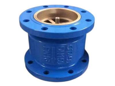
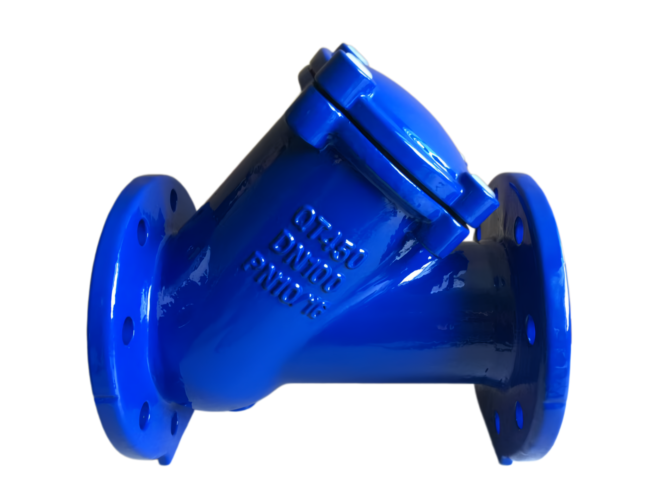
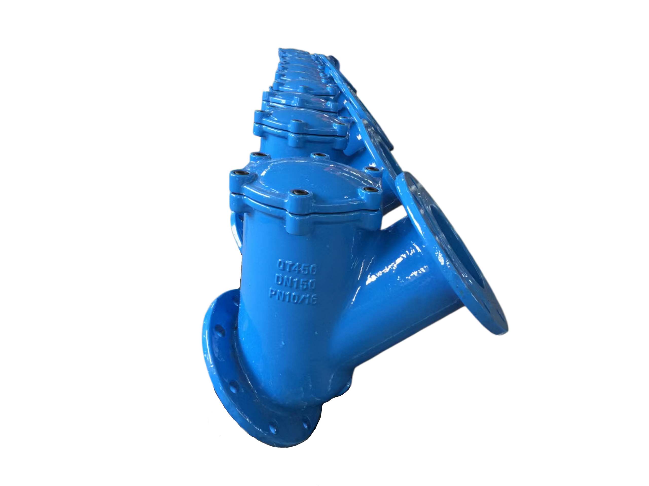
Ball Check Valve, Ductile Iron Body, Rubber Ball
Technical Data Sheet
1. Product Description
This is a ball-type check valve featuring a ductile iron body and a rubber ball. It opens by the thrust of the flowing medium and closes by the ball’s own weight and reverse flow pressure, providing reliable non-return functionality. The design is simple with a smooth flow passage, making it particularly suitable for media containing suspended solids such as sewage and slurry. It is not prone to clogging or jamming.
2. Key Features
Body: Made of Ductile Iron (DI), offering high strength and superior impact resistance compared to grey cast iron.
Ball: Fully encapsulated or solid wear-resistant rubber ball, ensuring excellent sealing performance with no metallic impact noise during closure.
Full-bore or reduced-bore flow passage design for minimal head loss.
Internal mechanism has no shafts, pins, or springs, reducing potential failure points and making maintenance simple.
Suitable for horizontal or vertical installation (vertical installation requires upward flow direction).
3. Technical Specifications
Item Specification
Nominal Diameter (DN) 50 – 300 mm (other sizes available on request)
Nominal Pressure (PN) PN10 / PN16 (1.0 / 1.6 MPa)
Suitable Media Clean water, sewage, seawater, slurries with particles, weak acid/alkali solutions, etc.
Media Temperature -10 °C to +80 °C (EPDM rubber)
-20 °C to +80 °C (NBR rubber)
Test Pressure (Shell/Seat) Shell: 1.5 × PN; Seat: 1.1 × PN
Working Pressure ≤ PN rating
Connection Type Flanged ends (standards conforming to EN 1092-2 / GB/T 17241.6)
Face-to-Face Dimension According to ISO 5752 short series / GB/T 12221
Installation Orientation Horizontal installation / Vertical installation (flow must be upward)
4. Materials of Construction
No. Component Material Specification/Note
1 Body Ductile Iron QT450-10 / EN-GJS-450-10
2 Cover Ductile Iron QT450-10 / EN-GJS-450-10
3 Ball NBR or EPDM Solid rubber or steel core with rubber lining, selected based on media
4 Seat Sealing Face Integral with body, matching rubber ball Metal-to-rubber soft sealing
5 Fasteners Zinc-plated Carbon Steel / Stainless Steel Grade 8.8 / A2-70
6 Cover Gasket Non-asbestos fiber sheet / EPDM –
Rubber Material Selection Guide:
EPDM (Ethylene Propylene Diene Monomer): Suitable for municipal sewage, clean water, weak acids/alkalis. Not resistant to oils.
NBR (Nitrile Butadiene Rubber): Suitable for oily wastewater, petrochemical effluents.
NR (Natural Rubber): High abrasion resistance, suitable for slurry and ore pulp.
5. Typical Dimensions and Weights (PN10/16)
Nom. Diameter DN Face-to-Face L (mm) Flange OD D (mm) Bolt Circle Dia. K (mm) Bolts No.-Dia. Approx. Height H (mm) Approx. Weight (kg)
50 200 165 125 4-Φ19 150 12
65 240 185 145 4-Φ19 165 16
80 260 200 160 8-Φ19 185 22
100 300 220 180 8-Φ19 210 35
125 350 250 210 8-Φ19 250 48
150 400 285 240 8-Φ23 280 65
200 500 340 295 8-Φ23 / 12-Φ23 340 110
250 600 395 / 405 350 / 355 12-Φ23 / 12-Φ28 400 180
300 700 445 / 460 400 / 410 12-Φ23 / 12-Φ28 460 260
*Note: Dimensions and weights shown are typical for PN10/PN16. Flange thickness increases slightly for PN16. Final dimensions are subject to approved drawings.*
6. Performance and Operating Requirements
Minimum Opening Pressure: Approx. 0.03 – 0.05 bar (0.3 – 0.5 m water column), resulting in low pressure loss.
Closing Differential Pressure: Sealing increases with back pressure. Full differential pressure sealing is permissible.
Recommended Flow Velocity: For continuous flow, ≤ 3 m/s (clean water); ≤ 2 m/s (media with particles).
Avoid: Do not use in conditions where the ball is suspended, or where severe oscillation occurs due to rapid, low-velocity flow reversal.
7. Installation and Maintenance Notes
Before Installation: Remove welding slag and debris from the pipeline. Ensure no foreign objects are inside the valve.
Direction: The arrow on the valve body must point in the direction of flow. For vertical installation, flow must be upwards only.
Gaskets: Use flange gaskets appropriate for the pressure rating. Tighten bolts evenly in a diagonal pattern.
Pressure Testing: During system strength testing, the valve must be kept in a half-open position to prevent single-sided pressure from damaging the ball.
Maintenance: If leakage occurs after extended operation, disassemble the cover and inspect the rubber ball for wear, deformation, or embedded debris. Replace the ball if necessary.
Storage: Store in a dry, ventilated area. The ball should remain in a free state, avoiding prolonged compression that may cause deformation.
8. Ordering Information
Please specify: Nominal Diameter, Pressure Rating, Rubber Material, Medium Type, Operating Temperature.
Example: Ball Check Valve, DN100, PN10, Ductile Iron Body, EPDM Ball, for sewage at ambient temperature.
This technical data sheet is for reference only. The manufacturer reserves the right to modify the design without prior notice.