API 6A 10000PSI Floating Ball Valve Suitable For Grayloc Hubs
Description
TECHNICAL DATA SHEET
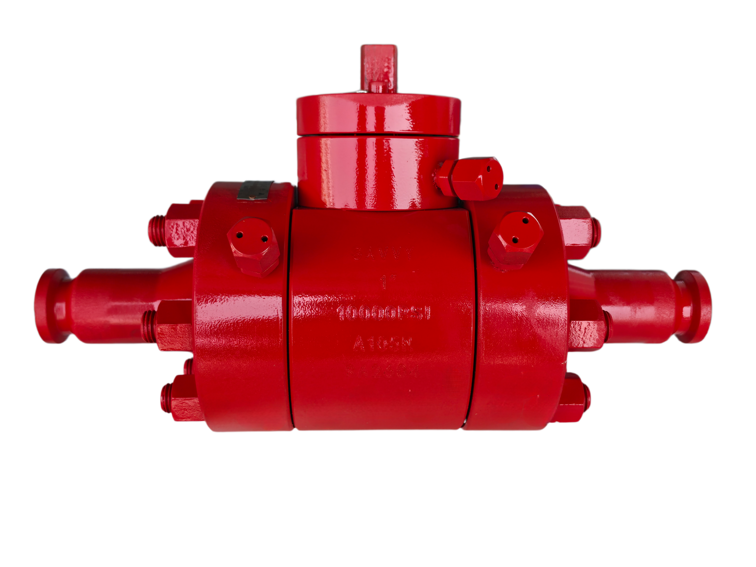
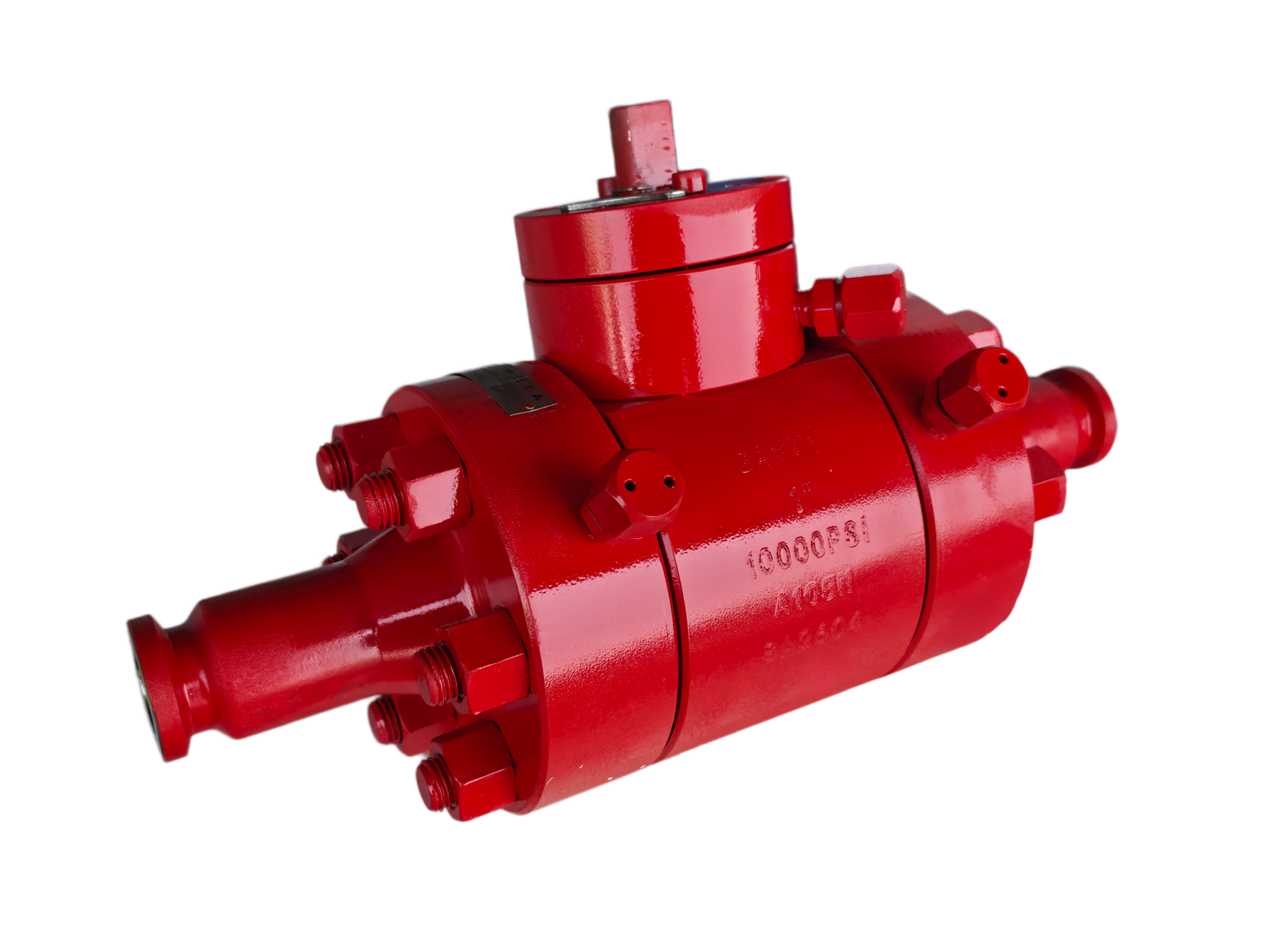
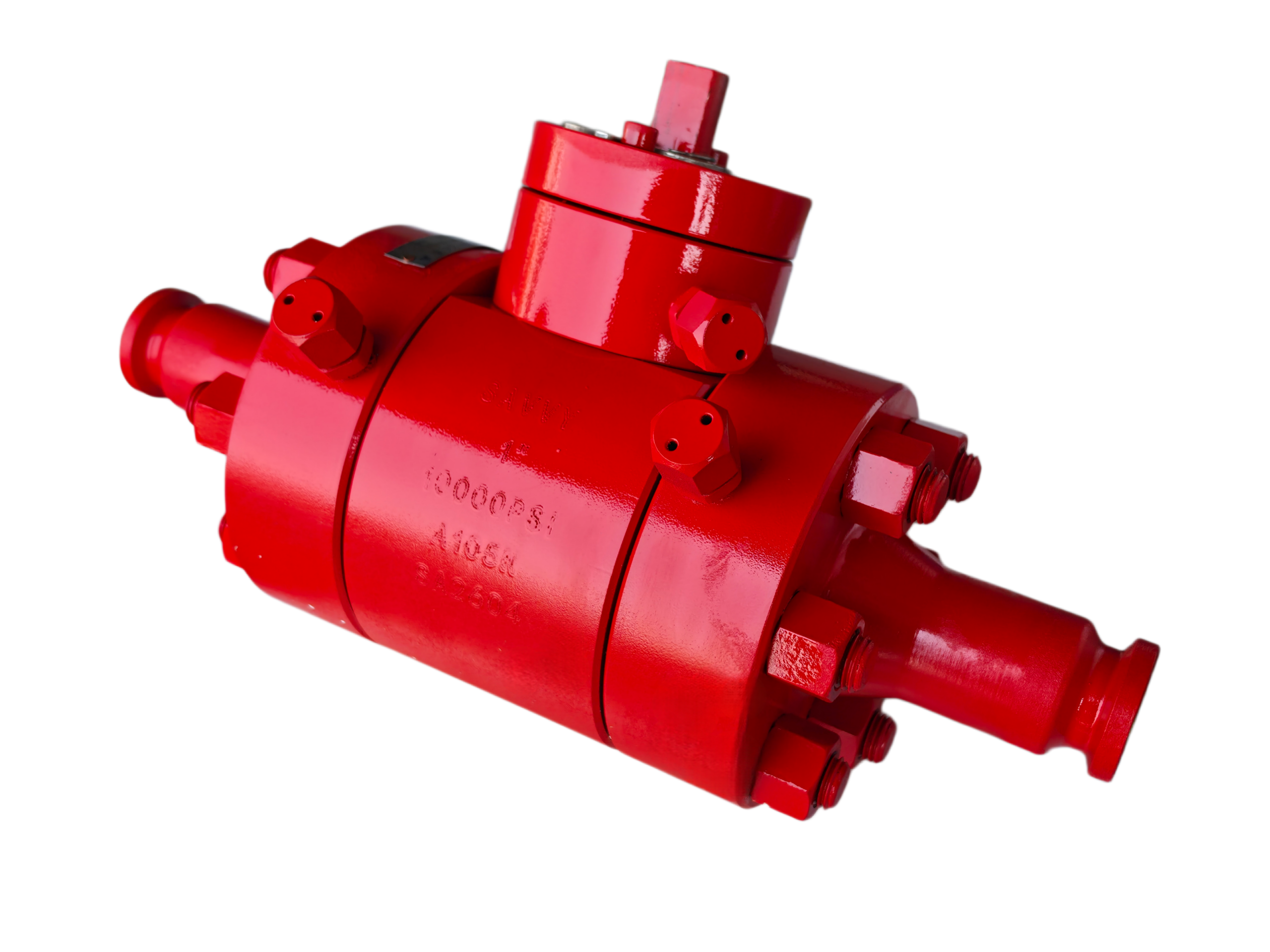
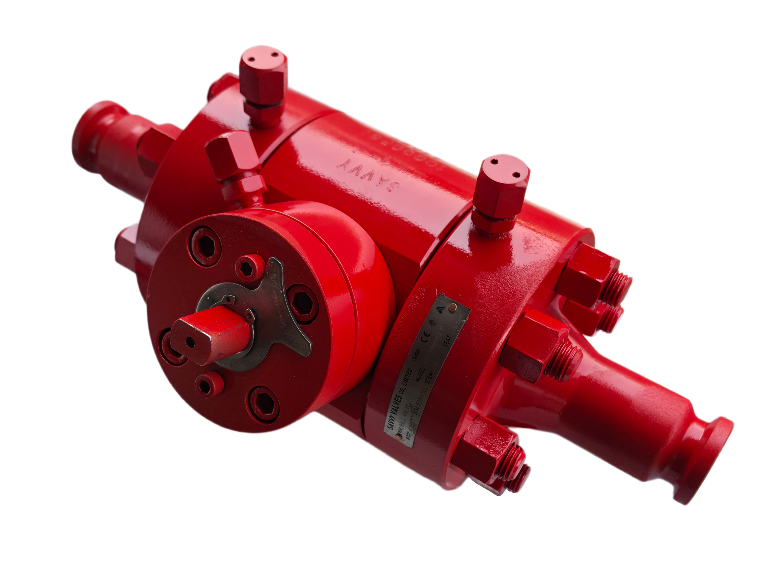
API 6A 10,000 PSI FLOATING BALL VALVE
Suitable for Grayloc® Hub Connections
DOCUMENT CONTROL
Item Description
Document Type Technical Data Sheet
Valve Type Floating Ball Valve
Design Standard API 6A / ISO 10423 (21st Edition)
Pressure Rating 10,000 PSI (690 bar)
End Connection Grayloc® Hub
Revision Status For Reference Only
1. GENERAL DESCRIPTION
This Technical Data Sheet covers the API 6A, 10,000 PSI Floating Ball Valve, specifically designed for integration with Grayloc® clamp-type hub connectors. The valve features a floating ball design, in which the ball is not mechanically fixed by trunnions but instead shifts slightly downstream under line pressure, compressing against the downstream seat to create a tight, reliable seal. The upstream seat serves a nominal function, making the valve inherently bidirectional in sealing capability.
This valve is engineered for moderate-sized, high-pressure oil and gas applications including wellhead equipment, Christmas trees (non-choke lines), high-pressure manifolds, process lines, and offshore platform piping systems—particularly where compact design, weight savings, and bidirectional sealing are required.
Note: For 10,000 PSI service, floating ball valves are typically limited to sizes ≤ 4″ (NPS). For larger bore sizes, a trunnion-mounted ball valve design is recommended.
2. TECHNICAL SPECIFICATIONS
Parameter Specification
Product Name API 6A Floating Ball Valve
Design Standard API 6A / ISO 10423 (21st Edition)
Valve Type Floating Ball Valve (Quarter-Turn)
Body Construction 2-Piece or 3-Piece Bolted / Forged Steel
Size Range 1/2″ to 4″ (DN 15 to DN 100); larger sizes upon consultation
Pressure Rating 10,000 PSI (690 bar / 69 MPa)
Bore Type Full Bore (Standard) or Reduced Bore
Flow Direction Bi-Directional
Temperature Class Class K (-60°C to +82°C) to Class U/V (-29°C to +121°C / up to +180°C) per API 6A
Product Specification Level (PSL) PSL 1, PSL 2, PSL 3, PSL 3G (Typical: PSL 3G)
Performance Requirement (PR) PR 1 (Standard) / PR 2 (High-Cycle, per API 6A Annex F)
Material Class AA, BB, CC, DD, EE, FF, HH (Sour Service per NACE MR0175: FF)
Shut-Off Classification Tight Shut-Off / Zero Leakage (Soft Seat) per API 598
End Connection Grayloc® Integral Hub for Clamp Connector
Operation Manual (Lever / Gear), Pneumatic, Electric, Hydraulic
Design Life Per API 6A service requirements
3. MATERIALS OF CONSTRUCTION
All materials comply with NACE MR0175 / ISO 15156 for sour service (H₂S & CO₂) when specified. Material certificates per EN 10204 Type 3.1 / 3.2 are available upon request.
No. Component Standard Material (Sour Service) Optional Materials
1 Body / Bonnet ASTM A694 F60 / F65, AISI 4130 (NACE compliant) A182 F22 (Cr-Mo), A182 F316 (Stainless Steel), Duplex SS, Inconel 625
2 Ball 17-4PH SS + Coating / Hardfacing (e.g., NiCr, CrN) Inconel 625 + Stellite 6, Tungsten Carbide (HVOF)
3 Seat Reinforced PTFE, PEEK, Nylon, Devlon Metal-to-Metal with Graphite Filling
4 Stem 17-4PH SS / AISI 4140 (NACE compliant, ≤33 HRC hardness) Inconel 625, Monel
5 Bolting / Fasteners ASTM A193 B7 / A320 L7 (PTFE coated) Stainless Steel A193 B8M
6 Stem Packing PTFE / Graphite —
7 O-Ring / Secondary Seal FKM (Viton), HNBR, or FFKM —
8 Anti-Static Device Spring-loaded conductive element —
9 Handle / Lever Carbon Steel with Epoxy Coating / Stainless Steel —
10 Gear Operator Housing Ductile Iron / Cast Steel (for gear-operated models) —
(Materials may be customized based on service media, temperature, and project-specific requirements.)
4. GRAYLOC® END CONNECTION SPECIFICATIONS
The valve is supplied with integral Grayloc® hubs suitable for mating with Grayloc clamp-type connectors. Grayloc clamp connectors use a metal-to-metal bore seal activated by clamp bolt tightening, providing high-integrity, zero-leakage sealing suitable for extreme pressure and temperature environments.
Parameter Specification
Connection Type Grayloc® Clamp Hub Connector
Hub Interface Integral Hub (welded or machined per valve body configuration)
Design Pressure Rating Full vacuum up to 60,000 psig (system rated for 10,000 psi)
Design Temperature Range -423°F to 1,700°F (-253°C to 927°C)
Sealing Mechanism Metal-to-Metal Bore Seal (Self-Energizing)
Clamp Assembly 2 Hubs + 1 Metal Seal Ring + 1 Pair Clamps + 4 Sets Bolts & Nuts
Key Advantages High-integrity sealing; weight & space savings vs. RTJ flanges (up to 70% less bolt torque); quick assembly; no bolt-hole alignment required
Applicable Standards Designed per ASME Section VIII, API 6A; ASME B31.1, B31.3, B31.4, B31.8, B31.12
Hub Materials Nickel alloys, carbon steel, low-alloy steel, stainless steel, duplex stainless steel
Seal Ring Materials Nickel alloys, low-alloy steel, stainless steel, duplex stainless steel
Grayloc Hub Interface Note: Hubs are manufactured per Grayloc standards and can be customized for blind, reduced port, or instrument connections. The floating ball valve‘s inherently low torque requirement makes it especially compatible with clamp-type connections.
5. APPLICABLE STANDARDS & CERTIFICATIONS
Category Standard / Code
Design & Manufacture API 6A / ISO 10423 (21st Edition)
Pressure-Temperature Rating API 6A, ASME B16.34
End Connections Grayloc Hub (per Grayloc Standard); ASME B16.5 (Flanged); ASME B16.25 (Buttweld)
Face-to-Face Dimension ASME B16.10 or Manufacturer’s Standard
Inspection & Testing API 598, API 6A
Fire-Safe Certification API 6FA / API 607 / BS 6755 Part 2
Fugitive Emissions ISO 15848-1 (Class BH) (Optional)
Sour Service NACE MR0175 / ISO 15156
Product Specification Level PSL 1 to PSL 4 (PSL 3G typical)
Performance Requirement PR 1 / PR 2 (with Annex F testing)
Marking API Monogram (upon request), CE PED (upon request)
SIL Capability (Optional) IEC 61508 SIL 2 / SIL 3
Pressure Equipment Directive 2014/68/EU (PED)
6. DESIGN FEATURES
6.1 Floating Ball Mechanism
The ball is not fixed by trunnions. Under pressure, the ball shifts slightly downstream, compressing the downstream seat and creating a tight seal. The upstream seat is only a nominal fit, providing a self-relieving cavity pressure relief mechanism when upstream pressure exceeds seat loading.
6.2 Bidirectional Sealing
The floating design provides sealing against pressure from either direction, with the downstream seat acting as the primary seal in both flow directions.
6.3 Anti-Blowout Stem
The stem is retained integrally in the bonnet, preventing ejection under high pressure—a critical safety feature for wellhead and high-pressure applications.
6.4 Anti-Static Device
Spring-loaded conductive elements ensure electrical continuity across the ball, stem, and body, preventing static charge accumulation in explosive atmospheres.
6.5 Fire-Safe Design
Certified to API 6FA / API 607. In the event of fire and seat degradation, secondary metal-to-metal sealing surfaces provide emergency shut-off capability.
6.6 Low Operating Torque
Fewer moving parts (no trunnion bearings) means torque is generally lower than trunnion designs at smaller sizes, reducing actuator size and cost.
6.7 Cavity Pressure Relief
For floating ball valves, the cavity is normally self-relieving through the upstream seat when cavity pressure exceeds seat loading, eliminating the need for an external relief valve in most applications.
6.8 Emergency Sealant Injection
Fittings (if specified) allow injection of emergency sealant into seat and stem areas for temporary sealing under emergency conditions.
7. TESTING & INSPECTION REQUIREMENTS
All testing is performed in accordance with API 6A requirements.
Test Type Requirement / Procedure
Body Shell Hydrostatic Test 1.5 × Rated Pressure = 15,000 PSI (1,034 bar) – no leakage through pressure boundary
Seat Hydrostatic Test (High Pressure) 1.1 × Rated Pressure = 11,000 PSI (758 bar) – zero leakage (both directions)
Seat Gas Test (Low Pressure) 80 – 160 PSI (5.5 – 11 bar) – bubble-tight for soft-seated valves
Double Block & Bleed (DBB) Per API 6A – cavity venting capability verified (optional for floating ball design)
PR2 Performance Validation High-cycle / hyperbaric testing per API 6A Annex F (if required)
Non-Destructive Examination (NDE) Magnetic Particle Inspection (MPI) / Liquid Penetrant Inspection (LPI) / Radiographic Testing (RT) – extent per PSL requirements
Fire Test API 6FA / API 607 certification (if specified)
Fugitive Emission Test ISO 15848-1 Class BH (if specified)
Inspection Standard API 598 (Valve Inspection and Test)
Additional Testing Available:
Low-Temperature Testing per API 6A Class K / L / T requirements
Helium Leak Detection for critical gas service
Hyperbaric Testing for subsea applications
8. PERFORMANCE DATA
8.1 Pressure-Temperature Rating (API 6A 10,000 PSI Class)
Temperature Class Temperature Range Maximum Working Pressure
Class K -60°C to +82°C (-76°F to +180°F) 10,000 PSI (690 bar)
Class L -46°C to +82°C (-51°F to +180°F) 10,000 PSI (690 bar)
Class P -29°C to +82°C (-20°F to +180°F) 10,000 PSI (690 bar)
Class U -29°C to +121°C (-20°F to +250°F) 10,000 PSI (690 bar)
Class V -18°C to +180°C (0°F to +356°F) Consult manufacturer
*(Pressure-temperature ratings per API 6A / ASME B16.34. For applications exceeding standard temperature classes, consult factory.)*
8.2 Cv (Kv) Flow Coefficients (Full Bore, Approximate)
Nominal Size Bore Diameter (Approx.) Cv Value (Fully Open) Breakaway Torque (Dry, Approx.)
1/2″ (DN 15) 13 mm 12 15 N·m
3/4″ (DN 20) 19 mm 25 20 N·m
1″ (DN 25) 25 mm 45 30 N·m
1-1/2″ (DN 40) 38 mm 110 50 N·m
2″ (DN 50) 50 mm 200 80 N·m
3″ (DN 80) 76 mm 480 180 N·m
4″ (DN 100) 100 mm 850 320 N·m
(Cv values are indicative and measured with water at 15°C – 25°C. Torque values are breakaway torques with dry media at zero differential pressure. Actual values may vary with pressure, medium, temperature, and seat material.)
9. DIMENSIONAL DATA (Grayloc Hub End, 10,000 PSI)
Nominal Size Face-to-Face A (mm) Valve Height – Open B (mm) Hub Outer Dia. (Approx., mm) Approx. Weight (kg)
1/2″ (DN 15) 165 180 95 5.5
3/4″ (DN 20) 190 195 115 8.0
1″ (DN 25) 216 210 135 11.5
1-1/2″ (DN 40) 267 245 170 19.0
2″ (DN 50) 292 270 205 28.0
3″ (DN 80) 356 325 260 48.0
4″ (DN 100) 432 380 320 72.0
*(Dimensions are indicative and based on manufacturer’s standard. Certified dimensional drawings with full hub profile details, bolt circle dimensions, and clamp specifications are available upon request. Face-to-face dimensions per ASME B16.10 or manufacturer‘s standard.)*
10. ACTUATION & ACCESSORIES
10.1 Manual Operation
Lever Handle: Lockable lever handle for sizes ≤ NPS 2 (DN 50)
Gear Operator: Bevel gear operator for sizes ≥ NPS 3 (DN 80); includes position indicator
Chain Wheel Operator: Available for elevated installations
10.2 Automated Actuation
Pneumatic: Double-acting or spring-return (fail-safe) configurations; Scotch yoke or rack & pinion
Electric: Explosion-proof (Ex-d / Ex-e) or weatherproof; on-off or modulating control
Hydraulic: Direct hydraulic or electro-hydraulic actuation for remote / subsea applications
10.3 Control Accessories
Limit Switch Boxes (mechanical / proximity / inductive)
Solenoid Valves (NAMUR mount, ATEX / IECEx certified)
Positioners (analog 4–20 mA / digital / HART / Foundation Fieldbus)
ESD (Emergency Shutdown) Systems
Manual Override (declutchable gear)
Hydraulic Override for redundancy
10.4 Actuator Mounting
ISO 5211 compliant top mounting flange for direct actuator installation
11. ADDITIONAL OPTIONS & ACCESSORIES
Seat Materials: Virgin PTFE, Glass-Reinforced PTFE (RPTFE), PEEK, Devlon, Nylon, Metal-to-Metal with hardfacing (Stellite, Tungsten Carbide, Chrome Carbide)
Ball Coatings: Electroless Nickel Plating (ENP), Chrome Plating, Tungsten Carbide (HVOF), Stellite Overlay
Body/Bonnet Materials: Carbon Steel (A694 F60/F65), Low-Alloy Steel (AISI 4130), Stainless Steel (A182 F316), Duplex / Super Duplex Stainless Steel, Inconel 625, Inconel 825
Elastomer Seals: HNBR, FKM (Viton), FFKM (Kalrez / Chemraz), EPDM
Fire-Safe Certification: API 6FA / API 607
Fugitive Emission Certification: ISO 15848-1 Class BH
SIL Certification: IEC 61508 SIL 2 / SIL 3 (with certified actuator package)
NACE Compliance: NACE MR0175 / ISO 15156 (Materials for Sour Service)
Special Coatings: Offshore-grade external epoxy coating (primer + topcoat); internal anti-corrosion coating per NACE
Stem Extension: For buried service or insulated pipelines
Locking Device: Open / closed position lockout for process safety
12. SERVICE CONDITIONS & APPLICATIONS
12.1 Service Media
Crude Oil
Natural Gas
Well Fluids (including produced water)
Water / Glycol Injection
Hydraulic Fluids
Fluids containing H₂S and/or CO₂ (Sour Service per NACE MR0175)
12.2 Typical Applications
Wellhead Equipment and Christmas Trees (non-choke lines)
High-Pressure Manifolds and Flowlines
Offshore Platforms and FPSO Topsides
Subsea Production Systems
Grayloc Hub-Based Piping Systems
Hydraulic Control Panels
Chemical Injection Skids
High-Pressure Gas Compression
Pipeline Pig Launchers and Receivers
12.3 Grayloc Integration Benefits
The compact, lightweight design of a floating ball valve is optimally matched with Grayloc hub connections for weight-sensitive, space-constrained topside and subsea applications. The reduced bolt torque requirement (up to 70% less than equivalent RTJ flanges) simplifies field installation and maintenance.
13. ORDERING INFORMATION
To specify or order, please provide the following information:
Valve Type: API 6A Floating Ball Valve with Grayloc Hub Ends
Size: [e.g., 2″ / DN 50]
Pressure Rating: 10,000 PSI
Bore Type: [Full Bore / Reduced Bore]
Body Material: [e.g., A694 F65 / AISI 4130 / A182 F316]
Ball Material: [e.g., 17-4PH SS / Inconel 625]
Seat Material: [e.g., PEEK / RPTFE / Metal-to-Metal]
Temperature Class: [e.g., Class U (-29°C to +121°C)]
PSL Level: [e.g., PSL 3G]
Performance Requirement: [e.g., PR 1 / PR 2]
Material Class: [e.g., FF (Sour Service)]
Operation: [Manual Lever / Gear / Pneumatic / Electric / Hydraulic]
Service Medium: [e.g., Sour Gas with 3% H₂S, +80°C]
Optional Requirements: [Fire-Safe / NACE MR0175 / SIL / PR2 / ISO 15848 / Special Coatings]
Grayloc Hub Specification: [Hub size / clamp type / seal ring material]
Example Order Description
API 6A Floating Ball Valve, 10,000 PSI, 2″ (DN 50), Full Bore, Body A694 F65, Ball 17-4PH SS with ENP Coating, PEEK Seat, Class U (-29°C to +121°C), PSL 3G, PR 1, Material Class FF, Grayloc Hub Ends, Fire-Safe per API 6FA, NACE MR0175 Compliant.
14. DOCUMENTS & REFERENCE CODES
Document / Code Description
Design Basis API 6A / ISO 10423 (21st Edition)
Pressure-Temperature ASME B16.34
Face-to-Face ASME B16.10 or Manufacturer’s Standard
End Connections (Alternative) ASME B16.5 (Flanged), ASME B16.25 (Buttweld)
Grayloc Design Grayloc Standard; ASME Section VIII Div. 1, 2 & 3
Sour Service NACE MR0175 / ISO 15156
Fire Safety API 6FA / API 607 / BS 6755 Part 2
Testing API 598, API 6A
Marking MSS SP-25, API Monogram (upon request)
DISCLAIMER:
The information contained in this Technical Data Sheet is for general reference purposes only. Specifications, dimensions, and performance data are subject to change without notice. For critical applications, please contact the manufacturer or supplier for certified engineering documentation, material test certificates (e.g., EN 10204 Type 3.1 / 3.2), and project-specific compliance verification. The user is responsible for verifying the suitability of the valve for the intended service conditions. For sizes above 4″ (NPS 100) in 10,000 PSI class, a trunnion-mounted ball valve is recommended.