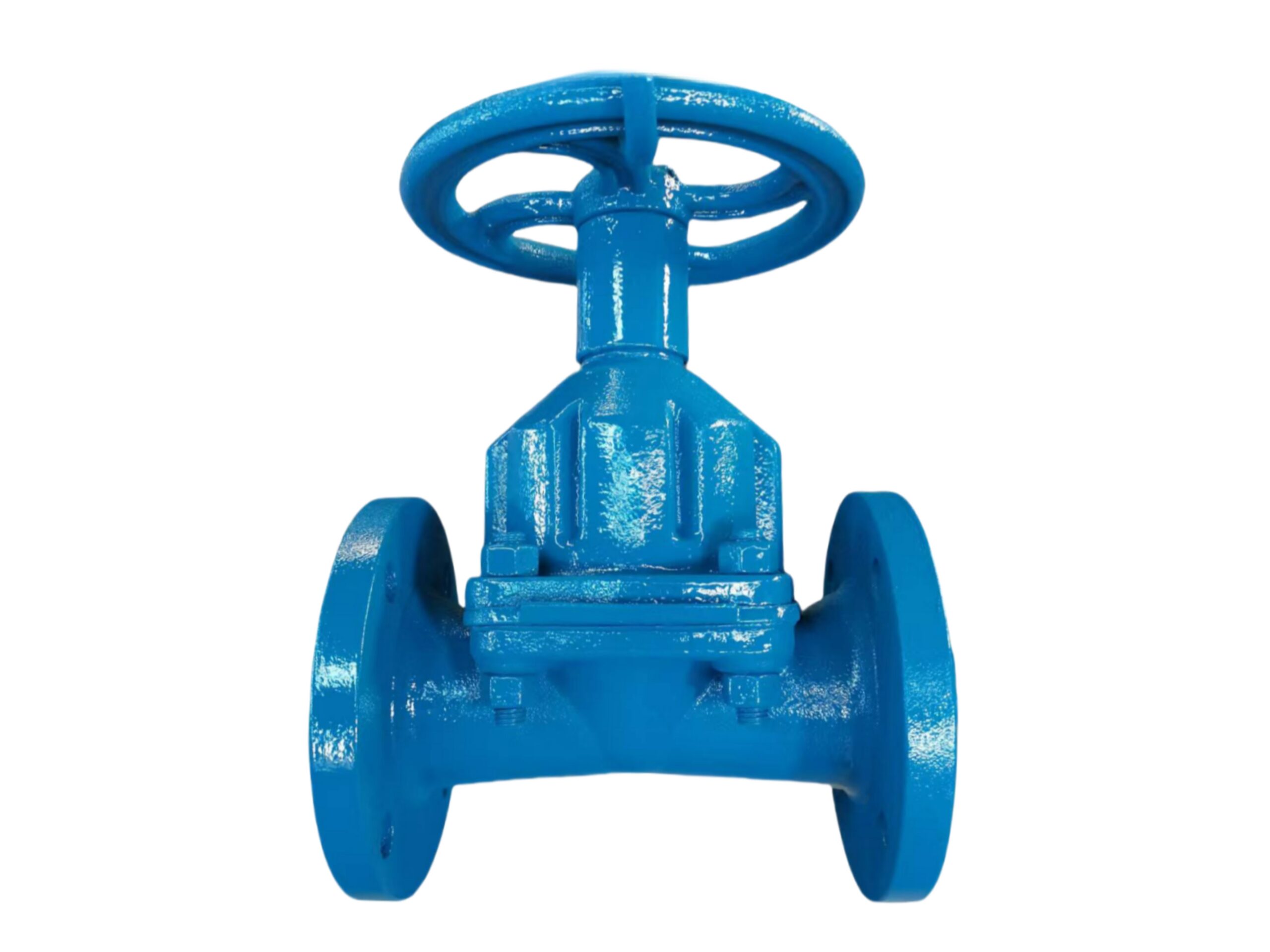
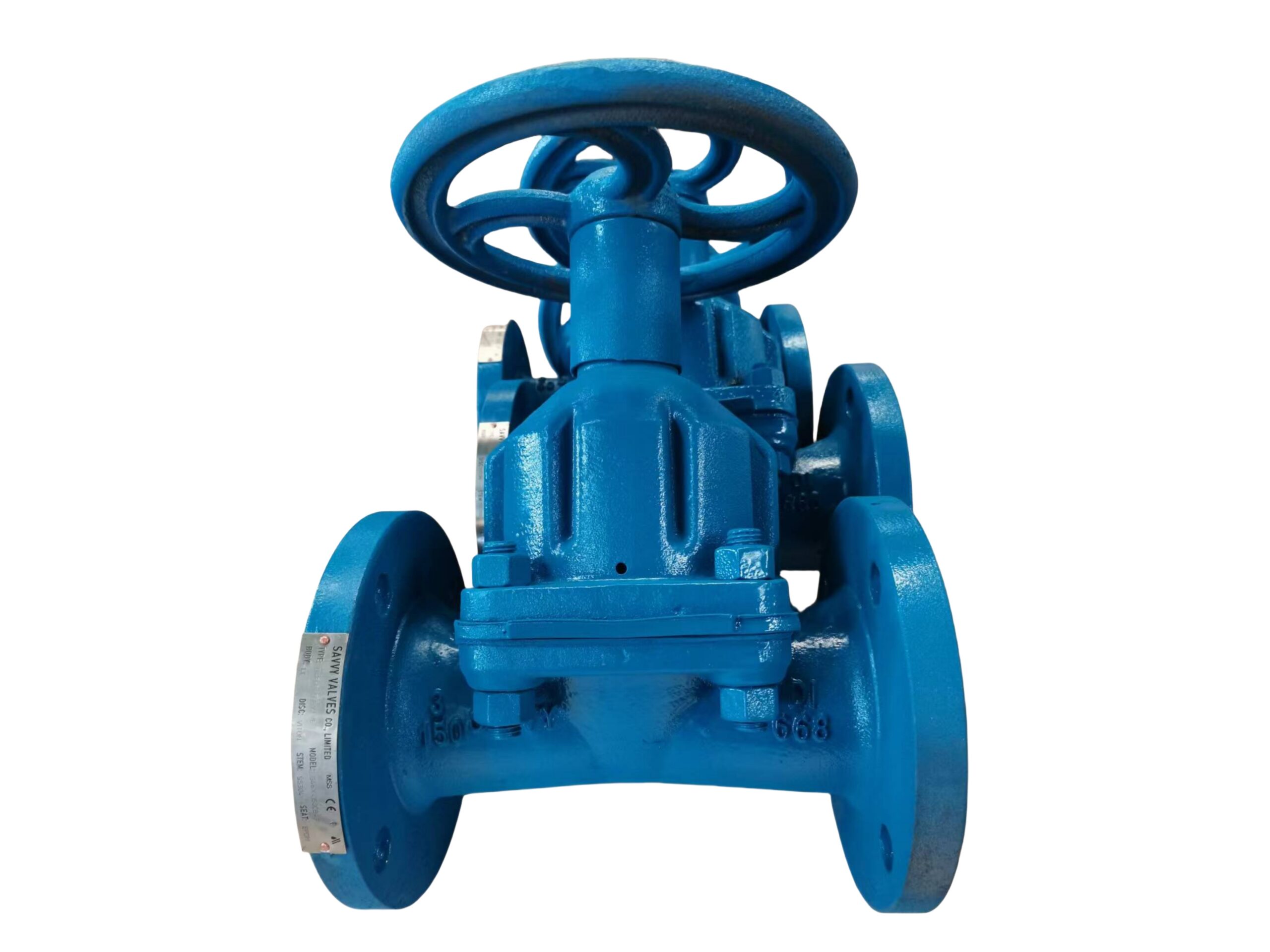
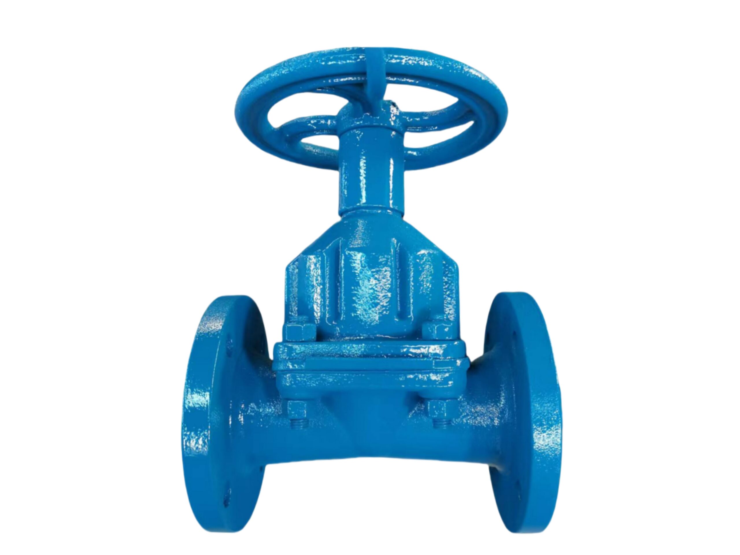
Rubber Lined Diaphragm Valve
Description
TECHNICAL DATA SHEET
Rubber Lined Diaphragm Valve
Weir-Type, Full-Bore, Cast Iron Body, 150LB, Flanged Ends
1. GENERAL DESCRIPTION
The weir-type diaphragm valve features a cast iron body with a full internal rubber lining and a reinforced rubber diaphragm. The bonnetless design uses the diaphragm as both the closing element and body-bonnet seal, completely isolating the operating mechanism from the process fluid. The valve provides bubble-tight shutoff, excellent throttling performance, and superior chemical and abrasion resistance. The rising stem and handwheel give clear visual position indication. It is suited for corrosive chemicals, abrasive slurries, water treatment, and high-purity applications where metal contact with the fluid must be avoided.
2. DESIGN FEATURES
-
Full-Body Rubber Lining: The entire wetted interior of the cast iron body is lined with a selected elastomer, providing full protection against corrosion and erosion. No metal parts are exposed to the fluid.
-
Weir-Type Body: The raised saddle in the center of the flow path allows for a compact, efficient sealing area and simplifies lining, ensuring complete shutoff with minimal diaphragm deformation.
-
Reinforced Rubber Diaphragm: Multi-layer fabric-reinforced diaphragm provides high strength, flexibility, and long service life. The diaphragm fully isolates the bonnet and stem from the process fluid.
-
Rising Stem & Positive Shutoff: Visible position indication is combined with precise, bubble-tight closure even in slurry or fibrous media.
-
Bonnet-Free Maintenance: The diaphragm can be inspected or replaced without removing the valve body from the pipeline; simply detach the bonnet.
-
Slurry & Corrosion Resilience: The streamlined rubber-lined flow path minimizes fluid acceleration, reducing wear and particle impingement.
3. APPLICABLE STANDARDS
| Category | Standard |
|---|---|
| Design & Manufacturing | MSS SP-88 (Diaphragm Type Valves) |
| Face-to-Face Dimensions | MSS SP-88 (Standard & Short Pattern) |
| Flange Connection | ASME B16.1 Class 125 (Compatible with ASME B16.5 Class 150) |
| Pressure–Temperature Ratings | In accordance with ASME B16.42 / MSS SP-88 (limited by elastomer) |
| Testing & Inspection | API 598 (Shell & Seat Leakage) |
| Lining & Diaphragm Materials | As per manufacturer’s quality standards |
4. TECHNICAL SPECIFICATIONS
| Parameter | Value |
|---|---|
| Nominal Size | 2″ – 12″ (DN50 – DN300) |
| Pressure Class | 150LB (ASME Class 125 / 150 equivalent) |
| Maximum Working Pressure | 10 bar (150 psi) at 21°C (for standard rubber linings) |
| Shell Test Pressure | 1.5 x MWP (15 bar / 225 psi) |
| Seat Leakage Test | 1.1 x MWP (11 bar); Bubble-tight (zero visible leakage) |
| Standard Temperature Range | Depending on lining/diaphragm (see Section 7), typically -10°C to +85°C |
| Flow Direction | Bi-directional |
| Operation | Manual Handwheel (Standard); Pneumatic or Electric actuation optional |
| Lining/ Diaphragm Options | Natural Rubber, EPDM, Butyl, Hypalon, Nitrile, Viton (dependent on chemical) |
5. BILL OF MATERIALS (BOM)
| No. | Component | Material | Standard / Grade |
|---|---|---|---|
| 1 | Body | Cast Iron (Gray Iron) | ASTM A126 Class B / GG25 |
| 2 | Body Lining | Rubber (selected per service) | EPDM / NR / Butyl / Neoprene / Viton |
| 3 | Diaphragm | Fabric-Reinforced Rubber | Matched to lining material, reinforced with nylon/polyester |
| 4 | Compressor (Disc) | Ductile Iron / Epoxy Coated Iron | GJS-500-7 / A536 |
| 5 | Stem | Stainless Steel | ASTM A276 Type 304 |
| 6 | Bonnet / Cover | Cast Iron | ASTM A126 Class B (epoxy painted) |
| 7 | Handwheel | Cast Iron | GG25, epoxy painted |
| 8 | Stem Nut (Yoke Bushing) | Brass / Bronze | CZ132 / C95400 |
| 9 | Fasteners | Stainless Steel | ASTM A2-70 (304) |
| 10 | Identification Plate | SS 304 | — |
Note: For severe chemical services, the compressor can be encapsulated in plastic (PP/PVDF) or fully rubber-covered. The selected rubber grade must match the temperature and chemical of the process.
6. DIMENSIONS (Class 150 / 125 Flanged, Short Pattern per MSS SP-88)
| Size (in / DN) | Face-to-Face L (mm) | Open Height H ≈ (mm) | Handwheel Dia. (mm) | Approx. Weight (kg) |
|---|---|---|---|---|
| 2″ (DN50) | 190 | 210 | 140 | 9 |
| 3″ (DN80) | 230 | 275 | 180 | 16 |
| 4″ (DN100) | 292 | 340 | 200 | 26 |
| 6″ (DN150) | 356 | 425 | 300 | 48 |
| 8″ (DN200) | 406 | 520 | 355 | 78 |
| 10″ (DN250) | 521 | 625 | 400 | 115 |
| 12″ (DN300) | 572 | 725 | 500 | 165 |
Note: H is height from pipe centreline to top of handwheel with valve fully open. Dimensions are for standard manual valves; gear operators are recommended for sizes 8″ and above. Weights are approximate and depend on lining type.
7. PRESSURE–TEMPERATURE RATING (Typical for EPDM / Natural Rubber lining)
The maximum working pressure is dependent on the lining material and temperature. Standard ratings:
| Temperature (°C) | Max. Working Pressure – EPDM (bar) | Max. WP – Natural Rubber (bar) |
|---|---|---|
| -10 to +40 | 10 | 10 |
| +60 | 8.5 | 8.0 |
| +80 | 7.0 | 6.0 |
| +100 | 5.5 | 4.5 |
Note: For Butyl, Hypalon, or Viton linings, higher temperatures may be possible. Always confirm with manufacturer’s elastomer compatibility chart. The valve is not designed for temperatures below the lining’s brittleness point.
8. TESTING & INSPECTION
Each valve undergoes the following tests according to API 598:
-
Shell Hydrostatic Test: 15 bar (225 psi) water for minimum 60 seconds, no leakage or deformation.
-
Seat Leakage Test: 11 bar (165 psi) water/air, bubble-tight closure required. Zero visible leakage permitted.
-
Diaphragm Integrity Check: Visual inspection of rubber thickness and physical check for pinholes (spark test on lining if specified).
-
Optional: Pneumatic shell and seat tests, thickness measurement of lining, chemical resistance certificates.
9. COATING & CORROSION PROTECTION
-
Body Exterior: High-build epoxy paint, RAL 5015 (Sky Blue) or RAL 5017 (Traffic Blue), minimum DFT 150 μm. Alternative colors available.
-
Bonnet & Handwheel: Two-component epoxy paint over sandblasted surface, chemical resistant.
-
Bolts & Nuts: Stainless steel for corrosion resistance.
10. ACCESSORIES & OPTIONS
-
Gear Operator: Bevel gearbox recommended for sizes 8″ and above to reduce handwheel torque.
-
Limit Switches: Proximity or mechanical type for remote open/close indication.
-
Positioner and Actuator: Pneumatic (double-acting or fail-safe) or electric actuators for automated control. Standard ISO 5211 mounting flange.
-
Chain Wheel: For overhead operation.
-
Bare Stem / Square Nut: For buried or extended spindle applications.
-
Special Linings: Conductive PTFE/PFA for high-purity or conductive service, or extra thick rubber for highly abrasive slurries.
-
Drain Port: Tapped drain in body for cleaning and condensate removal (optional on weir-type).
11. NOTES
-
Rubber-lined diaphragm valves are designed for corrosive and abrasive services. The elastomer must be selected based on chemical compatibility and operating temperature. EPDM is suitable for many acids, alkalis, and water; natural rubber for abrasive slurries; butyl for strong acids.
-
Ensure the pipeline is clean to avoid mechanical damage to the rubber lining.
-
Do not use in vacuum service unless specially designed and specified, as vacuum may cause lining collapse or diaphragm detachment.
-
Fully open/close the valve within the permissible pressure rating; avoid throttling near the closed position for extended periods to maximize diaphragm life.
-
When installing, do not use the handwheel as a lifting point. Support the valve by the body and pipeline.
-
For automated or high-cycle applications, consult factory for diaphragm life expectancy and maintenance intervals.
This data sheet presents standard product information. We reserve the right to update specifications without prior notice. Certified drawings, EN 10204 3.1 material certificates, and rubber compound test reports can be furnished upon request.